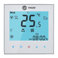
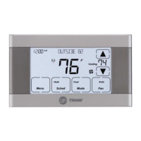
The TR-SAS908MTW-0-F3 is a digital DX thermostat designed for controlling two-stage compressor systems. It features a large LCD display with a backlight, allowing for simultaneous display of set points and room temperature.
Function Description:
This thermostat is engineered to maintain the temperature within a precise range of 0.5°C to the set point. It offers flexible fan control with both "on" and "auto" modes, and supports manual changeover between heating and cooling. A key feature is its ability to retain user settings even after a power-off event, as it does not require a battery for this function. The device also includes a display temperature recalibration feature, a sleep mode option for energy saving, and compressor short cycling protection to extend the lifespan of the compressor.
Important Technical Specifications:
- Input Voltage: 100-240VAC 50/60Hz
- Fan Relay Amps inductive: 8A
- Cool Relay Amps inductive: 1A
- Set point Temperature Range: 5°C to 35°C
- Temperature Correction Factor: -3°C to 3°C
- Accuracy: ±0.5°C
- Dimensions: 115mm × 90mm × 28mm
Wiring Diagram Details:
The wiring diagram illustrates connections for a 220VAC common power supply. It includes inputs for a 100K NTC sensor (S2, S1), and outputs for 2nd Stage Cooling (Y2) and 1st Stage Cooling (Y1), both rated for 1A (0.5A inductive). Fan control outputs are provided for High (H), Medium (M), and Low (L) speeds, each rated for 8A (5A inductive). The main power input is (L, N) 100-240VAC 50/60Hz.
Usage Features:
The thermostat's interface includes several buttons and indicators for ease of use:
- Power button: To turn the device on or off.
- System switch (NOP): For system mode selection.
- Fan switch (AUTO H,M,L): To select fan operation mode (Auto, High, Medium, Low).
- Sleep operation button: To activate sleep mode.
- Reset switch: To reset the device.
- Temperature setting buttons: To raise or lower the temperature setting.
- Room temperature display: Shows the current ambient temperature.
- Hidden parameter display: For advanced settings.
- System mode display: Indicates the current operating mode (e.g., Cool, Heat).
- "Cool on" indicator: Illuminates when the thermostat is calling for cooling.
- Sleep mode indicator: Shows when sleep mode is active.
- Fan switch position indicator: Displays the current fan speed setting.
- Setting temperature display: Shows the desired temperature.
- Key lock: A feature to prevent unauthorized changes to settings.
Installation Process:
Installation involves several straightforward steps:
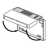
- Disassembly: Remove the two screws from the bottom of the thermostat and gently pull the control panel straight off the base. Avoid forcing or prying to prevent damage.
- Wiring: Connect wires beneath the terminal screws on the power supply module according to the provided wiring schematic (Figure 4, not included in the provided document but referenced).
- Mounting Power Base: Push the power base into the wall or an 86mm x 86mm conduit box.
- Securing Power Base: Use two mounting screws to secure the power base to the wall. Use a level against the bottom of the base to ensure it is level, then tighten the screws. Leveling is primarily for appearance and does not affect thermostat operation.
- Reassembly: Replace the control panel onto the power base and secure it by reinserting the two screws removed in step 1.
The device is designed for mounting to a conduit box, with screws provided for both the thermostat itself and for fixing the control panel and power base.