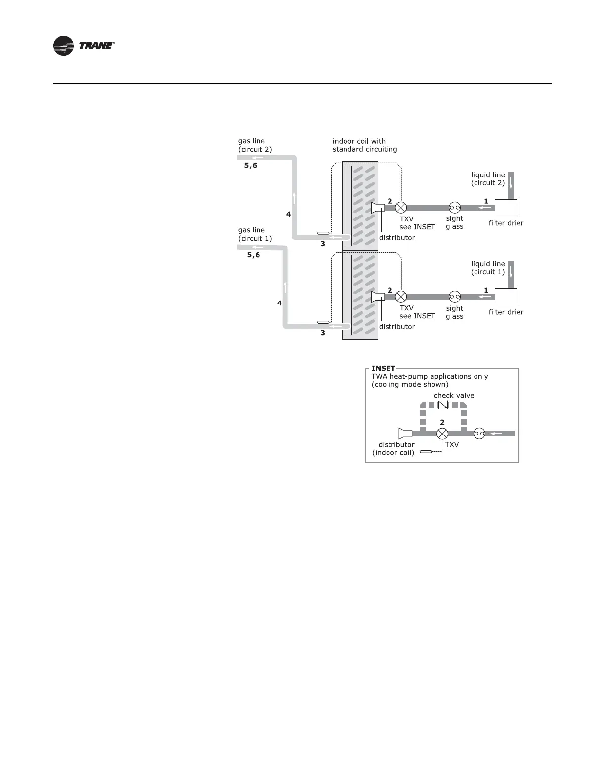
Figure 12. Indoor coil with two distributors (dual-circuit TTA/TWA units)
1 Pitch the liquid line 1 inch per 10 feet (1 cm per
3 m) so that the liquid refrigerant drains toward
the indoor coil. Use the liquid-line size
recommended in Table 2, p. 20, or Table 3, p. 21.
2 Provide one expansion valve (TXV)
per distributor.
TWA heat pumps only: Provide one check
valve for each expansion valve.
3 Pitch the gas line leaving the coil so that it
slopes away from the coil by 1 inch per 10 feet
(1 cm per 3 m).
4 For vertical risers, use the tube diameter
recommended in Ta ble 2 or Ta b l e 3 . Ensure that
the top of the riser is at least 1 foot (30 cm)
above the lowest point.
5 Pitch the gas line 1 inch per 10 feet (1 cm per
3m) toward the indoor coil.
6 Insulate the gas line.