EasyManua.ls Logo

Trane TTPO30D User Manual

Trane TTPO30D
8 pages
To Next Page IconTo Next Page
Page #1 background imageLoading...
Page #1 background image
TIMN£
It's Hard To Stop A Trane?
INSTALLER'S
G
TTP-IN-1D
18-AC34D1-5
Library Service Literature
Product Section Unitary
Product Split System Cooling
Model TTP
Literature Type Installer's Guide
Sequence 1D
Date June 2000
File No. SV-UN-S/S-TTP-IN-1D 6/00
Supersedes TTP-IN-1C
Model:
TTP018-024C, TTP030-O48D &TTPO60E Condensing Units
IMPORTANT -- This Document is customer property and is to remain with this unit. Please return to service information pack
upon completion of work.
These instructions do not cover all variations in systems
nor provide for every possible contingency to be met in
connection with installation. All phases of this installa-
tion must comply with NATIONAL, STATE AND LOCAL
CODES. Should further information be desired or should
particular problems arise which are not covered sufficiently fbr
the purchaser's purposes, the matter should be referred to your
installing deal or local distributor.
GENERAL
The following instructions cover TTP018-024C, TTP030-048D &
TTP060E Condensing Units.
NOTICE: These outdoor units may be used with indoor
units equipped with Capillary Tube, Thermostatic Ex-
pansion Valve or the Accutron TM Flow Control Check
Valve (F.C.C.V.) assembly for refrigerant flow control.
Check fbr transportation damage after unit is uncrated. Report
promptly, to the carrier, any damage found to the unit.
To determine the electrical power requirements of the unit, refer
to the nameplate of the unit. The electrical power available nmst
agree with that listed on the nameplate.
B. LOCATION & PREPARATION OF THE UNIT
1. The unit should be set on alevel support pad at least as large
as the unit base pan.
2. The support pad must NOT be in direct contact with any
structure. Unit nmst be positioned a minimmn of 12" from any
wall or su rrou nding shrubbery to insure adequ ate airflow. Clear-
ance must be provided in f_ont of control box (access panels) &
any other side requiring service access to meet National Electri-
cal Code. Also, the unit location must be far enough away fi'om
any structure to prevent excess roofrun-offwater from pouring
directly on the unit.
3. The top discharge area must be unrestricted fbr at least five
(5) feet above the unit.
4. When the outdoor unit is mounted on a roof, be sure the roof
will support the unit's weight. Properly selected isolation is
recommended to prevent transmission to the building structure.
(_ TOP DISCHARGE--- UNRESTRICTED
5 FT. ABOVE UNIT
5. The maximum length of refrigerant lines fi'om outdoor to
indoor unit should NOT exceed sixty (60) feet.
6. If outdoor unit is mounted above the air handler, maximum
lift should not exceed sixty (60) fbet (suction line). If air handler
is mounted above condensing unit, maximum lift should not
exceed sixty (60) feet (liquid line).
NOTE: Refer to R@'igerant Piping Software, Pub. No. 22-3312-01.
7. Locate and install indoor coil or air handler in accordance
with instruction included with that unit.
Since The Trane Company has a policy of continuous
product and product data improvement, it reserves the
right to change design and specifications without notice.
© American Standard Inc 2000 Pub. No. 18-AC34D1-5
Question and Answer IconNeed help?

Do you have a question about the Trane TTPO30D and is the answer not in the manual?

Trane TTPO30D Specifications

General IconGeneral
BrandTrane
ModelTTPO30D
CategoryHeat Pump
LanguageEnglish

Summary

B. LOCATION & PREPARATION OF THE UNIT

Unit Placement and Clearances

Details pad requirements, clearances, and roof mounting for optimal airflow.

Refrigerant Line Length Limits

Specifies maximum refrigerant line lengths and lift for proper system operation.

C. ACCUTRONTM FLOW CONTROL VALVE

Orifice Size Determination and Adjustment

Explains how to determine and adjust the Accutron orifice size for system performance.

D. INSTALLING REFRIGERANT LINES

Refrigerant Line Routing and Securing

Guides on running, bending, securing, and isolating refrigerant lines to prevent noise and damage.

E. SERVICE VALVE OPERATION

Liquid and Gas Line Valve Procedures

Details the operation and precautions for both liquid and gas line service valves.

BRAZING REFRIGERANT LINES

Brazing Preparation and Techniques

Outlines steps for preparing and brazing refrigerant lines, including safety and purging.

LEAK CHECK

Leak Detection and Repair

Details the process for checking refrigerant lines for leaks using nitrogen and soap bubbles.

SYSTEM EVACUATION

Evacuation Procedure and Requirements

Describes the steps for evacuating the refrigerant lines and indoor coil to the correct micron level.

F. ELECTRICAL CONNECTIONS

Power Wiring and Grounding

Details requirements for power wiring, grounding, disconnect switches, and conduit.

Control Wiring Guidelines

Provides guidelines for low voltage control wiring lengths and thermostat installation.

G. COMPRESSOR SUMP HEAT

Sump Heat Activation and Procedure

Explains the activation of compressor sump heat and the required procedure before initial start-up.

H. OPERATIONAL AND CHECKOUT PROCEDURES

System Checkout and Service Facts

Refers to detailed operational and checkout procedures found in the Service Facts for proper performance.

TTP018-060 OUTLINE DRAWING

Unit Dimensions and Clearances

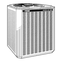
Provides outline drawing, dimensions, and critical clearance requirements for the TTP018-060 models.

Service Valve Connections

Illustrates the gas and liquid line service valve connections, including port types and sizes.

CHECKOUT PROCEDURE

Pre-Operation System Checks

Lists essential checks to perform after installation completion before system operation.

SYSTEM OPERATIONAL CHECK

Compressor Sump Heat and Operation

Details the procedure for checking system operation, including sump heat activation and pressure readings.

CHECKOUT PROCEDURE WITH MAIN POWER DISCONNECTS CLOSED (ON)

System Component Operation Verification

A table detailing component operations based on thermostat settings and power status.

Related product manuals