INSTALLER'S GUIDE
©
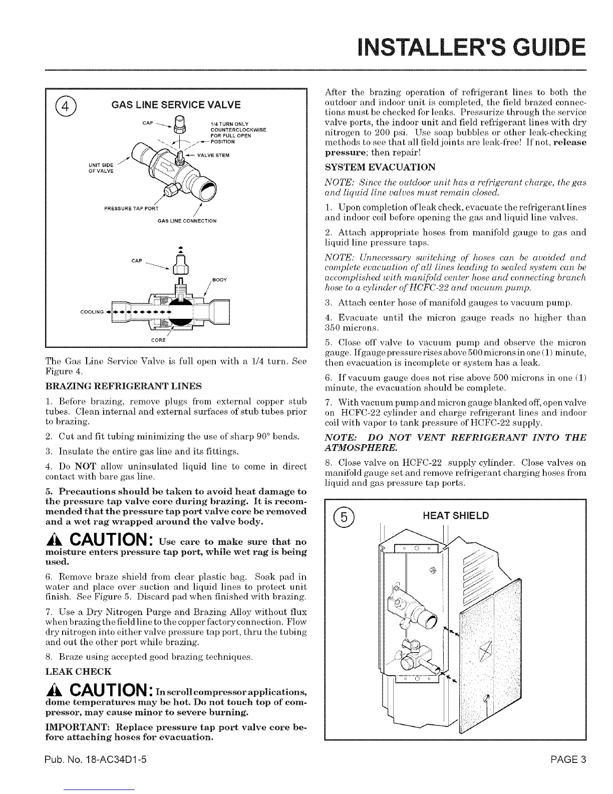
GAS LINE SERVICE VALVE
CAP _ _ 1/4 TURN ONLY
COUNTERCLOCKWISE
UNIT SIDE
OF VALVE
#
PRESSURE TAP PORT j
/
GAS LINE CONNECTION
cAP_
CORE
The Gas Line Service Valve is full open with a 1/4 turn. See
Figure 4.
BRAZING REFRIGERANT LINES
1. Before brazing, remove plugs from external copper stub
tubes. Clean internal and external surfaces of stub tubes prior
to brazing.
2. Cut and fit tubing minimizing the use of sharp 90 ° bends.
3. Insulate the entire gas line and its fittings.
4. Do NOT allow uninsulated liquid line to come in direct
contact with bare gas line.
5. Precautions should be taken to avoid heat damage to
the pressure tap valve core during brazing. It is recom-
mended that the pressure tap port valve core he removed
and a wet rag wrapped around the valve body.
CAUTION: Use care to make sure that no
moisture enters pressure tap port, while wet rag is being
used.
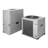
6. Remove braze shield from clear plastic bag. Soak pad in
water and place over suction and liquid lines to protect unit
finish. See Figure 5. Discard pad when finished with brazing.
7. Use a Dry Nitrogen Purge and Brazing Alloy without flux
when brazing the field line to the copper factory connection. Flow
dry nitrogen into either valve pressure tap port, thru the tubing
and out the other port while brazing.
8. Braze using accepted good brazing techniques.
LEAK CHECK
CAUTION :In scrollcompressorapplications,
dome temperatures may be hot. Do not touch top of com-
pressor, may cause minor to severe burning.
IMPORTANT: Replace pressure tap port valve core be-
fore attaching hoses for evacuation.
After the brazing operation of refrigerant lines to both the
outdoor and indoor unit is completed, the field brazed connec-
tions must be checked fbr leaks. Pressurize through the service
valve ports, the indoor unit and field refl_igerant lines with dry
nitrogen to 200 psi. Use soap bubbles or other leak-checking
methods to see that all field joints are leak-fl'ee! If not, release
pressure; then repair!
SYSTEM EVACUATION
NOTE: Since the outdoor unit has a refrigerant charge, the gas
and liquid line valves must remain closed.
1. Upon colnpletion ofleak check, evacu ate the refrigerant lines
and indoor coil befbre opening the gas and liquid line valves.
2. Attach appropriate hoses froJn manififld gauge to gas and
liquid line pressure taps.
NOTE: Unnecessary switching of hoses can be avoided and
complete evacuation of'all lines leading to sealed system can be
accomplished with mani[bld center hose and connecting branch
hose to a qylinder of HCFC-22 and vacuum pump.
3. Attach center hose of manifbld gauges to vacuum pump.
4. Evacuate until the micron gauge reads no higher than
350 microns.
5. Close off valve to vacuum pump and observe the micron
gauge. Ifgaugepressurerisesabove 500micronsinone (1) minute,
then evacuation is incomplete or system has a leak.
6. If vacuum gauge does not rise above 500 microns in one (1)
minute, the evacuation should be complete.
7. With vacuum pump and micron gauge blanked off, open valve
on HCFC-22 cylinder and charge rel?igerant lines and indoor
coil with vapor to tank pressure of HCFC-22 supply.
NOTE: DO NOT VENT REFRIGERANT INTO THE
ATMOSPHERE.
8. Close valve on HCFC-22 supply cylinder. Close valves on
manifold gauge set and remove refrigerant charging hoses from
liquid and gas pressure tap ports.
HEAT SHIELD
Pub. No. 18-AC34D1-5 PAGE 3