I STALLER'S GUIDE
@
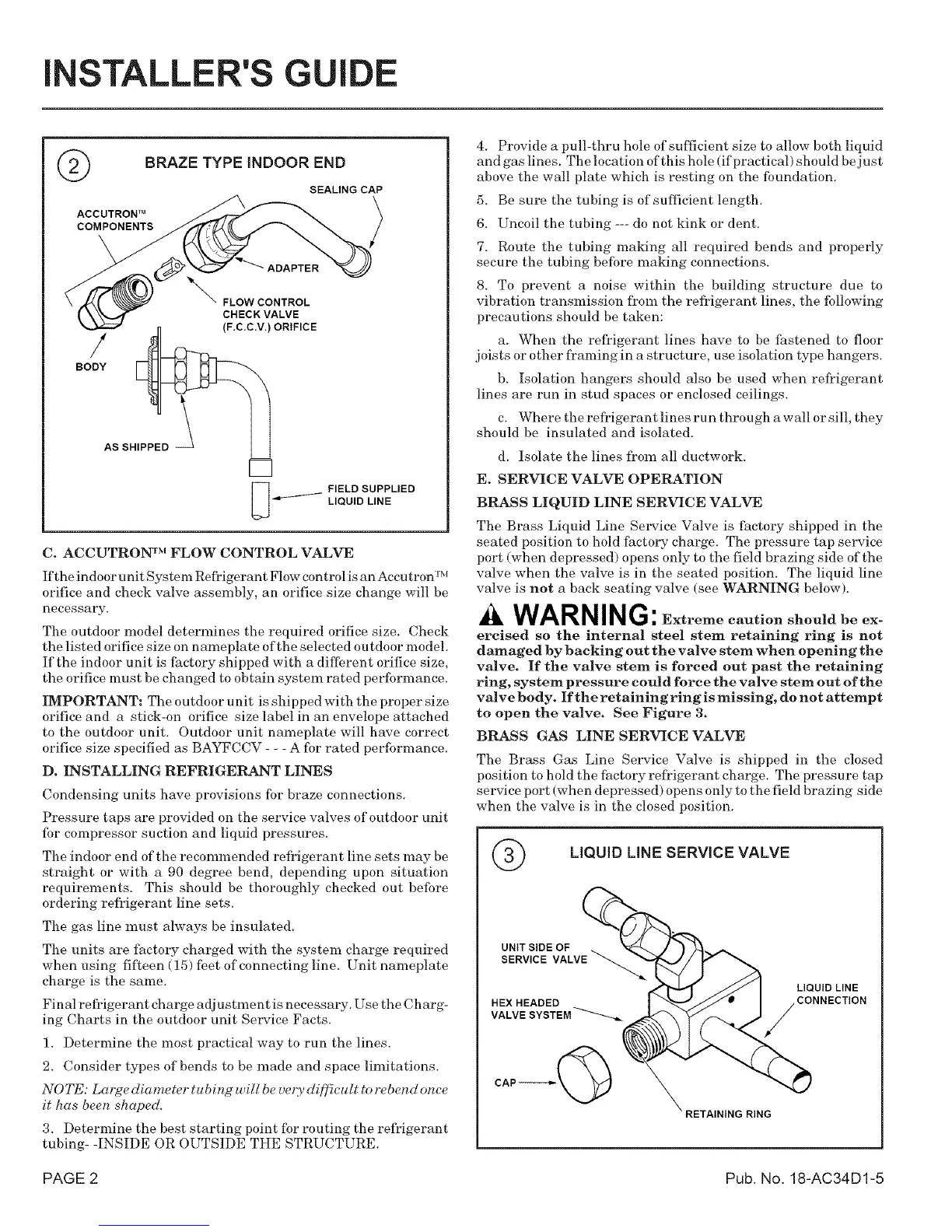
BRAZE TYPE iNDOOR END
SEALING CAP
ACCUTRON TM
COMPONENTS
/
BODY
_'_ FLOW CONTROL
CHECK VALVE
(F.C.C.V.) ORIFICE
AS SHIPPED -_
FIELD SUPPLIED
LIQUID LINE
C. ACCUTRON TM FLOW CONTROL VALVE
c_ IM
If the indoor unit Syste In Refi'i_ erant F1ow control is an Accu tron-
orifice and check valve assembly, an orifice size change will be
necessary.
The outdoor model determines the required orifice size. Check
the listed orifice size on nameplate of the selected outdoor model.
If the indoor u nit is factory shipped with a dilIbrent orifice size,
the orifice must be changed to obtain system rated performance.
IMPORTANT: The outdoor u nit is shipped with the proper size
orifice and a stick-on orifice size label in an envelope attached
to the outdoor unit. Outdoor unit nameplate will have correct
orifice size specified as BAYFCCV - - - A fbr rated performance.
D. INSTALLING REFRIGERANT LINES
Condensing units have provisions for braze connections.
Pressure taps are provided on the service valves of outdoor unit
fbr compressor suction and liquid pressures.
The indoor end of the recommended refrigerant line sets may be
straight or with a 90 degree bend, depending upon situation
requirements. This should be thoroughly checked out before
ordering refl'igerant line sets.
The gas line must always be insulated.
The units are factory charged with the system charge required
when using fif_een (15) feet of connecting line. Unit nameplate
charge is the same.
Final refrigerant charge adjustment is necessary. Use the Charg-
ing (?harts in the outdoor unit Service Facts.
1. Determine the most practical way to run the lines.
2. Consider types of bends to be made and space limitations.
NOTE: Large diameter tubing will be very di[f_cult to rebend once
it has been shaped.
3. Determine the best starting point fbr routing the refl_igerant
tubing- -INSIDE OR OUTSIDE THE STRUCTURE.
4. Provide a pull-thru hole of suflicient size to allow both liquid
and gas lines. The location of this hole (if practical) should be just
above the wall plate which is resting on the foundation.
5. Be sure the tubing is of sufficient length.
6. Uncoil the tubing --- do not kink or dent.
7. Route the tubing maMng all required bends and properly
secure the tubing before making connections.
8. To prevent a noise within the building structure due to
vibration transmission fl_oln the refrigerant lines, the following
precautions should be taken:
a. When the refl'igerant lines have to be fastened to floor
joists or other fl'aming in a structure, use isolation type hangers.
b. Isolation hangers should also be used when refrigerant
lines are run in stud spaces or enclosed ceilings.
c. Where the refrigerant lines ru n through a wall or sill, they
should be insulated and isolated.
d. Isolate the lines fl'om all ductwork.
E. SERVICE VALVE OPERATION
BRASS LIQUID LINE SERVICE VALVE
The Brass Liquid Line Service Valve is factory shipped in the
seated position to hold factory charge. The pressure tap service
port (when depressed) opens only to the field brazing side of the
valve when the valve is in the seated position. The liquid line
valve is not a back seating valve (see WARNING below).
WARNING: Extremecautionshouldbeex-
ercisedso the internal steel stem retaining ring is not
damaged by backing out the valve stem when opening the
valve. If the valve stem is forced out past the retaining
ring, system pressure could force the valve stem out of the
valve body. If the retaining ring is missing, do not attempt
to open the valve. See Figure 3.
BRASS GAS LINE SERVICE VALVE
The Brass Gas Line Service Valve is shipped in the closed
position to hold the factory refl'igerant charge. The pressure tap
service port (when depressed) opens only to the field brazing side
when the valve is in the closed position.
LIQUID LiNE SERVICE VALVE
UNIT SIDE OF
SERVICE VALVE
HEX HEADED
CAP-----_
LIQUID LINE
CONNECTION
RING
PAGE 2 Pub. No. 18-AC34D1-5