Do you have a question about the Trane TTA Series and is the answer not in the manual?
Covers general warnings, cautions, notices, environmental concerns, responsible refrigerant practices, and required PPE.
Explains the application guide's content for TTA/TWA systems using R-410A refrigerant and POE oil.
Discusses traditional piping principles and major components of split air-conditioning systems.
Provides updated guidelines for liquid and suction lines for R-410A refrigerant, including pressure drops and velocities.
Focuses on minimizing distance between components for optimal system performance and refrigerant charge.
Details proper sizing, slope, and insulation requirements for liquid refrigerant lines.
Details proper sizing, slope, and insulation requirements for gas refrigerant lines, focusing on oil return.
Explains the function, selection, and adjustment of expansion valves for proper refrigerant distribution.
Discusses system control options like Relia Tel and thermostat control, and stability requirements.
Explains the use and implications of hot gas bypass (HGBP) versus Evaporator Defrost Control (EDC).
Provides guidance on converting existing systems to R-410A, POE oil, and compatible components.
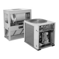
Illustrates typical refrigerant piping arrangements for TTA and TWA split systems with various indoor coil configurations.
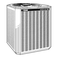
This document is an application guide for Trane TTA and TWA split systems, specifically focusing on tube size and component selection for units ranging from 6 to 20 tons that utilize R-410A refrigerant. It provides comprehensive guidelines for installing and servicing these air-conditioning systems, emphasizing best practices for reliable and efficient operation.
The primary function of this guide is to ensure the proper selection and installation of refrigerant piping and associated components. It addresses critical aspects such as minimizing refrigerant charge, maintaining oil return to the compressor, ensuring a column of liquid at the expansion valve, and minimizing capacity loss. The guide highlights that these systems are designed exclusively for R-410A refrigerant and POE oil, underscoring the importance of using R-410A rated service equipment and components due to the higher operating pressures compared to R-22.
Key usage features revolve around the meticulous design and installation of refrigerant lines. The guide provides updated guidelines for liquid and suction lines, emphasizing that while traditional piping practices remain relevant, the specific mass flows and pressures of R-410A necessitate different line diameters and potentially greater allowable pressure drops. For liquid lines, the guide recommends sizing to minimize pressure losses and limiting velocity to 600 ft/min to prevent water hammer. It also details routing requirements, suggesting a slight slope in the direction of flow and noting that insulation is generally not required unless routed through high-temperature areas. For suction lines, the guide stresses the importance of maintaining oil-entrainment velocities in both horizontal and vertical risers, with specific line sizes preselected to ensure proper oil return to the compressor.
Component selection is another crucial aspect covered. For liquid lines, necessary components include a filter drier, access port, moisture-indicating sight glass, and expansion valve(s). The guide specifies the proper sequence for positioning these components, ideally close to the indoor unit. It notes that TTA/TWA outdoor units come with a pre-installed filter drier, but for line lengths exceeding 80 ft, this drier should be removed and a new one installed near the indoor unit. TWA units, being heat pumps, require two liquid filters and two check valves due to reverse flow. Access ports are essential for charging and determining charge levels. The guide also discusses solenoid valves for isolating refrigerant in cooling-only systems, though it warns against their use in heat pumps and in systems already equipped with a check valve due to the risk of explosion from trapped liquid refrigerant. Moisture-indicating sight glasses are included for their moisture-indicating ability, though the manual's charging curves are recommended for determining charge levels.
Expansion valves are critical for metering refrigerant into the evaporator coil. The guide emphasizes selecting the correct size and type to ensure proper refrigerant distribution and prevent issues like compressor flooding or overheating. It recommends balanced port construction and external equalization for improved modulation and identifies specific part numbers for TTA/TWA systems. For heat pump operation, some expansion valve models have built-in check valves, or external check valves are required to bypass the TXV in heating mode.
For gas lines, proper sizing is essential to guarantee oil return to the compressor without excessively affecting capacity or efficiency. The guide suggests that two different line diameters may be necessary for horizontal runs/vertical drops and vertical lifts (risers). Routing instructions advise straight paths, avoiding unnecessary changes in direction, and installing the gas line with a slight slope towards the indoor coil. It explicitly warns against installing riser traps, clarifying that what appears to be a riser trap at the coil outlet is actually a design to drain the coil and prevent off-cycle condensed refrigerant from flowing to the compressor. The guide also advises against underground refrigerant lines due to potential issues with condensation, debris, and corrosion. Insulation is recommended for gas lines to prevent heat gain and condensation. An access port in the gas line allows for checking refrigerant pressure and superheat.
Maintenance features are implicitly woven throughout the installation guidelines. The emphasis on proper line sizing, component selection, and routing directly contributes to the long-term reliability and reduced maintenance needs of the system. The guide highlights the importance of minimizing refrigerant charge to improve system reliability and shorten service life. It also addresses the critical role of cleanliness during installation, with the liquid filter drier preventing contaminants from entering the expansion valve. For remodel, retrofit, or replacement scenarios, the guide provides extensive warnings and considerations. It stresses that the entire system must be reviewed for compatibility with R-410A and POE oil, including existing electrical service and protection. It details which existing copper lines are suitable for R-410A pressures and which need replacement with thicker walls. Reselecting expansion valves and replacing any gaskets or O-rings are also crucial. The guide strongly recommends removing original mineral oil from components not being replaced and emphasizes using dry nitrogen during brazing and only new containers of POE oil due to its hygroscopic nature.
The document also touches on controls, explaining that TTA/TWA units can use ReliaTel™ or thermostat control. It advises that if compressor staging is managed by a third party, system stability (5-minute-on, 5-minute-off, and 5-minute-interstage differentials) must be programmed to ensure proper operation and compressor protection. Finally, it discusses hot gas bypass (HGBP), advising against its use whenever possible due to increased refrigerant charge, potential leaks, and energy inefficiency, advocating instead for Evaporator Defrost Control (EDC) for coil protection.
| Refrigerant | R-410A |
|---|---|
| Voltage | 208/230V |
| Cooling Capacity | 1.5 to 5 tons |
| Heating Capacity | 1.5 to 5 tons |
| Sound Level | 72 dB |