EasyManuals Logo

Trane TWA120D User Manual

Trane TWA120D
28 pages
To Next Page IconTo Next Page
To Previous Page IconTo Previous Page
Page #21 background imageLoading...
Page #21 background image
SS-APG008-EN 15
Refrigerant Piping Examples
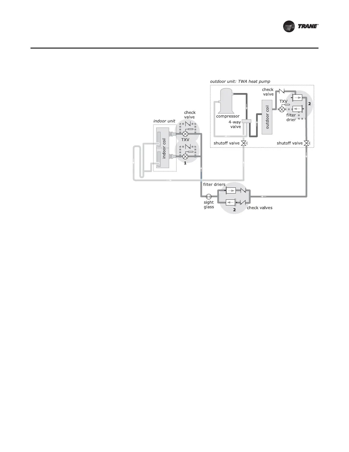
Figure 9. TWA heat pump and matched indoor coil (typical arrangement shown in cooling mode)
1 Each coil distributor requires one thermal
expansion valve (TXV) and one check valve. See
Table 3 and Table 4, p. 21, for
recommendations.
2 For applications where the length of the liquid
line exceeds 80 ft (24 m) and the heat pump will
start in the cooling mode, remove the liquid-line
filter driers from the TWA heat pump and install
new filter driers and check valves (Table 3, p. 21)
at the indoor unit.

Questions and Answers:

Question and Answer IconNeed help?

Do you have a question about the Trane TWA120D and is the answer not in the manual?

Trane TWA120D Specifications

General IconGeneral
Model NumberTWA120D
CategoryHeat Pump
HSPF8.2
Voltage208/230 V
Phase1
RefrigerantR-410A
Cooling Capacity12000 BTU/h
Heating Capacity12000 BTU/h

Related product manuals