UNT-IOM-6 87
Terminal Unit
Control (TUC)
The TUC is capable of operating
in either a standalone application
or interfacing with a Trane
Tracer
®
system. In addition,
Trane EveryWare
™ software is
available to edit the configuration
of the TUC.
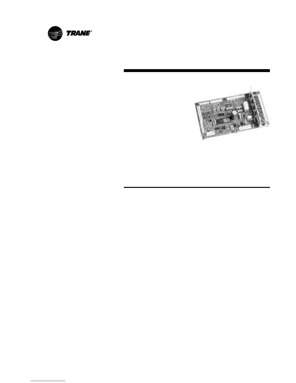
The TUC board is easily access-
ible on an isolation panel in the
control panel. The TUC board will
pivot down in the control panel
box after removing the screw on
the top right corner of the panel.
See Figure 29.
Figure 29. The TUC module
board.
TUC Sequence of Operations
Off: Fan is off; control valve options and fresh air damper options
close. The low air temperature detection option is still active.
Auto: Fan speed control in the auto setting allows the modulating
(three-wire floating point) control valve option and three-speed fan to
work cooperatively to meet precise capacity requirements, while
minimizing fan speed (motor/energy/acoustics) and valve position
(pump energy/chilled water reset). As the capacity requirement
increases at low fan speed, the water valve opens. When the low fan
speed capacity switch point is reached, the fan switches to medium
speed and the water valve repositions to maintain an equivalent
capacity. The reverse sequence takes place with a decrease in
required capacity.
Low/Med/High: The fan will run continuously at the selected speed
and the valve option will cycle to meet setpoint.