EasyManua.ls Logo

Trane FCLB User Manual

Trane FCLB
164 pages
To Next Page IconTo Next Page
Page #1 background imageLoading...
Page #1 background image
SAFETY WARNING
Only qualified personnel should install and service the equipment. The installation, starting up, and servicing
of heating, ventilating, and air-conditioning equipment can be hazardous and requires specific knowledge and
training. Improperly installed, adjusted or altered equipment by an unqualified person could result in death or
serious injury. When working on the equipment, observe all precautions in the literature and on the tags,
stickers, and labels that are attached to the equipment.
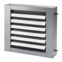
UniTrane™ Fan Coil and Force-Flo™ Cabinet Heater
200-1200 CFM
Models FC and FF
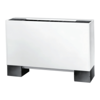
Low Vertical Models FCKB and FCLB
Installation, Operation,
and Maintenance
UNT-SVX07J-EN
June 2018

Table of Contents

Questions and Answers:

Trane FCLB Specifications

General IconGeneral
BrandTrane
ModelFCLB
CategoryHeater
LanguageEnglish

Summary

Installation—Mechanical

Installation Checklist

A step-by-step guide to ensure all mechanical installation procedures are completed.

Installing the Unit

Detailed instructions for properly installing vertical and horizontal units.

Coil Piping and Connections

Installation - Electrical

Supply Power Wiring

Guidance on sizing field wiring and fuses/breakers based on unit nameplate ratings.

ECM Overview and Setup

Installation and Initial Setup

Safety requirements and initial setup steps for ECM units, including wiring and configuration.

Startup

Pre-Startup Checklist

A checklist to verify all installation procedures are complete before unit startup.

Routine Maintenance

Diagnostics and Troubleshooting

Fan Coil and Cabinet Heater

Troubleshooting recommendations for common fan coil and cabinet heater symptoms and causes.

Wiring Diagrams

Table 95. Typical wiring diagram for ZN010 unit with single stage electric heat and unit mounted zone sensor

Detailed wiring diagram for ZN010 units with single-stage electric heat and zone sensors.

Table 96. Typical wiring diagram for UC400-B unit with dual stage electric heat and damper actuator

Detailed wiring diagram for UC400-B units with dual-stage electric heat and damper actuators.

Table 97. Typical wiring diagram for CSTI unit with 3-phase single-stage electric heat

Detailed wiring diagram for CSTI units with 3-phase single-stage electric heat.

Table 98. Typical wiring diagram ZN520 unit with 3-phase dual-stage electric heat and wireless zone sensor receiver

Detailed wiring diagram for ZN520 units with dual-stage electric heat and wireless zone sensors.

Table 99. Typical wiring diagram for Tracer® ZN520 unit with four-pipe configuration, condensate overflow switch, and wall-mounted zone sensor

Detailed wiring diagram for ZN520 units with four-pipe configuration, overflow switch, and zone sensor.

Table 100. Typical wiring diagram for Tracer® ZN510 unit with four-pipe configuration and split zone sensor/unit fan switch configuration

Detailed wiring diagram for ZN510 units with four-pipe config and split zone sensor/fan switch.

Related product manuals