Do you have a question about the Trane XR80 and is the answer not in the manual?
Certifications for natural and L.P. gas models per industry standards.
Solid-state control monitoring flame presence and dual solenoid gas valve.
Durable, heavy gauge aluminized steel heat exchanger for efficient heat transfer.
Multi-port in-shot burners designed for quiet and efficient service.
Solid-state control for total furnace operation, limits, and self-diagnostics.
4-speed blower motor providing airflow for heating/cooling needs.
Heavy gauge steel, wrap-around cabinet with baked-on enamel finish.
Adaptive hot surface ignition, front service access, and venter.
Comprehensive list of standard equipment included with the XR 80 furnace.
List of optional accessories and equipment available for the furnace.
Detailed technical specifications for various XR 80 furnace models.
Details furnace airflow (CFM) across various static pressures.
Wiring diagram for heating-only furnace operation.
Wiring diagram for single-stage heating and cooling operation.
Wiring diagrams for twin-stage heating-only furnaces with single wire twinning.
Wiring diagrams for twin-stage heat/cool furnaces with single wire twinning.
Outline drawing showing overall dimensions and connection points for TUD-C models.
Specifies minimum required clearances for safe installation of the furnace.
Provides wiring schematics and diagrams for gas furnaces.
Explains symbols and abbreviations used in the equipment diagrams.
Table detailing speed tap assignments for the induced draft fan motor.
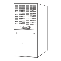
This document describes the Trane XR 80 Upflow/Horizontal Right or Upflow/Horizontal Left Induced Draft Gas Furnace, a single-stage fan-assisted combustion system designed for central heating.
The Trane XR 80 gas furnace is engineered to provide efficient and reliable heating for residential and light commercial applications. It operates as a central heating unit, drawing in air, heating it, and then distributing the warm conditioned air throughout the structure. The furnace is certified by both American and Canadian Gas Associations for use with natural gas, and all models can be converted to L.P. gas, offering flexibility in fuel source.
At its core, the furnace utilizes a single-stage fan-assisted combustion system. When there is a demand for heat from the room thermostat, the integrated system control initiates the heating sequence. This control employs an adaptive Hot Surface Ignition system, which is a key feature as it eliminates the need for a constant burning pilot light, thereby reducing energy waste. Once ignited, the main burners engage, and the durable, heavy-gauge aluminized steel heat exchanger quickly absorbs and transfers the heat to the circulating air.
The air delivery system is managed by a 4-speed, direct-drive blower motor. This motor is designed to provide sufficient airflow for a wide range of heating and cooling requirements. The blower motor's speed automatically adjusts, switching from heating to cooling speeds on demand from the room thermostat, ensuring optimal comfort and efficiency for both modes of operation. The furnace is designed for either upflow or horizontal right/left installations, providing versatility to fit various home layouts and existing ductwork configurations.
Safety is a paramount aspect of the Trane XR 80 furnace. The integrated system control continuously monitors for the presence of flame during heating operation, utilizing solid-state devices for reliable detection. An extra layer of safety is provided by a dual solenoid combination gas valve and regulator, which precisely controls the gas flow to the burners. Furthermore, a blower door safety switch is incorporated to prevent or terminate furnace operation if the blower door is removed, protecting users from potential hazards and ensuring proper functioning of the unit. The system also includes manual reset flame rollout switches and a manual reset burner box limit, which are critical safety components designed to detect and respond to abnormal combustion conditions. A vent proving pressure switch is also included to ensure proper venting of combustion byproducts.
The Trane XR 80 furnace is designed for user convenience and operational efficiency. Its "wrap-around" cabinet construction, made from heavy-gauge steel with a baked-on enamel finish, not only provides strength and durability but also contributes to the unit's aesthetic appeal. The heat exchanger section of the cabinet is completely lined with foil-faced fiberglass insulation, which serves a dual purpose: it enhances the quietness of operation by dampening noise and improves thermal efficiency by insulating the heated components.
The furnace offers flexible return air options, supporting alternate bottom, left, or right return air configurations, making it adaptable to different ducting setups. Gas connections can also be made from either the left or right side of the unit, further simplifying installation. The integrated system control is a central hub for operational management, providing total control over furnace limit sensors, blowers, and the gas valve. It also includes self-diagnostics, which can assist in troubleshooting and ease of service.
For enhanced indoor air quality and comfort, the furnace includes accessory hook-up capabilities for a humidifier and an Electronic Air Cleaner (EAC). These connection points allow for easy integration of additional systems to improve the overall indoor environment. The blower door is hinged for convenient access, and "Perfect Fit" door latches ensure a secure closure. A gasketed blower door further contributes to the unit's efficiency and quiet operation by sealing the blower compartment.
The furnace comes with cleanable high-velocity filters, which are standard filter sizes, offering a cost-effective and environmentally friendly solution for air filtration. An internal filter rack is also provided for easy filter management. The selectable cooling fan off delay is another user-friendly feature, allowing for customization of the fan's operation after a cooling cycle to optimize comfort and energy usage.
Maintenance of the Trane XR 80 furnace is designed to be straightforward and accessible. The complete front service access allows technicians to easily reach internal components for inspection, cleaning, and repairs. The slide-out blower assembly simplifies maintenance tasks related to the blower motor and fan, making it easier to clean or replace components as needed.
The multi-port in-shot burners are built for years of quiet and efficient service, and their design facilitates inspection and cleaning. The cleanable high-velocity filters are a significant maintenance advantage, as they can be washed and reused, reducing the need for frequent filter replacements and associated costs.
The integrated system control's self-diagnostics feature is a valuable tool for maintenance. It can help identify operational issues quickly, guiding technicians to the source of a problem and potentially reducing diagnostic time and repair costs. The inclusion of a 24-volt fuse provides protection for the low-voltage control circuit, and its easy accessibility allows for quick replacement if needed.
The furnace is backed by a non-prorated 20-year heat exchanger limited warranty, highlighting the manufacturer's confidence in the durability and longevity of this critical component. Additionally, a 5-year limited parts warranty covers other components, providing peace of mind for the owner regarding potential repair costs during the initial years of operation. These warranties underscore the robust design and expected reliability of the Trane XR 80 gas furnace.
| Type | Gas Furnace |
|---|---|
| Efficiency | 80% AFUE |
| Heating Stages | Single-stage |
| Blower Motor | Multi-speed |
| Ignition System | Hot Surface Ignition |
| Vent Type | Natural Draft |
| Heat Exchanger | Aluminized steel |
| Warranty | 5-year limited warranty on parts |