EasyManua.ls Logo

Trane YHC067E - User Manual

Trane YHC067E
84 pages
To Next Page IconTo Next Page
Loading...
Packaged Rooftop Air Conditioners
Precedent™ — Gas/Electric
3 to 10 Tons — 60 Hz
Installation, Operation, and Maintenance
January 2021
RT-SVX21AC-EN
Model Numbers:
YSC036G - YSC060G YHC072F - YHC102F
Model Numbers:
YSC072H - YSC120H YHC120F
Model Numbers:
YHC036E - YHC072E YHC037E - YHC067E
Model Numbers:
YHC048F - YHC060F
SAFETY WARNING
Only qualified personnel should install and service the equipment. The installation, starting up, and servicing of
heating, ventilating, and air-conditioning equipment can be hazardous and requires specific knowledge and training.
Improperly installed, adjusted or altered equipment by an unqualified person could result in death or serious injury.
When working on the equipment, observe all precautions in the literature and on the tags, stickers, and labels that are
attached to the equipment.

Table of Contents

Other manuals for Trane YHC067E

Question and Answer IconNeed help?

Do you have a question about the Trane YHC067E and is the answer not in the manual?

Trane YHC067E Specifications

General IconGeneral
Model NumberYHC067E
CategoryAir Conditioner
Cooling Capacity67, 000 BTU/h
Refrigerant TypeR-410A
Voltage208/230V
Phase3

Summary

Introduction

Warnings, Cautions, and Notices

Defines safety advisories (Warning, Caution, Notice) used throughout the manual.

Proper Field Wiring and Grounding Required!

Emphasizes qualified personnel for field wiring and grounding to prevent hazards.

Personal Protective Equipment (PPE) Required!

Stresses the necessity of wearing appropriate PPE for safety.

Model Number Descriptions - 3 to 10 Tons (T;Y)

Digit 1 - Unit Type

Explains the meaning of the first digit in the model number for unit type.

Digit 2 - Efficiency

Details the significance of the second digit for unit efficiency ratings.

Digit 14 - Fresh Air Selection

Describes options for fresh air intake based on model number digits.

General Information

Unit Inspection

Outlines procedures for inspecting the unit upon arrival for damage and compliance.

Storage

Provides precautions for storing the unit to prevent damage and condensate formation.

Unit Description

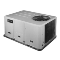
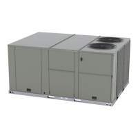
Gives an overview of the unit's construction, testing, and control system options.

Dimensions and Weights

Unit Clearances

Illustrates minimum clearances required for installation and service.

Heavy Objects!

Warns about hazards associated with lifting heavy units and equipment.

Improper Unit Lift!

Details risks of improper lifting and testing procedures for safe operation.

Installation

Foundation

Details requirements for unit installation foundations, including safety and structural integrity.

Ductwork

Shows supply and return air opening locations for various unit configurations.

Rigging

Provides safety warnings and instructions for lifting and rigging the unit.

Temperature Limit Switch Usage for Gas Heat Units

TCO1 Instructions for Low NOx Gas Furnace Option

Explains the location and function of the TCO1 limit switch for specific gas furnace options.

Horizontal Discharge Conversion (3 to 5 Ton Units)

Horizontal Discharge Conversion (6 to 10 Ton Units)

TCO1 Instructions

Describes how to replace the TCO1 limit control for units with different tripping values.

Main Electrical Power Requirements

Hazardous Voltage w;Capacitors!

Warns about hazards of disconnecting power and discharging capacitors before servicing.

Proper Field Wiring and Grounding Required!

Stresses the importance of qualified personnel for wiring and grounding.

Through-the-Base Gas Installation

Requirements for Gas Heat

Ultra Low NOx Gas Furnace Option - Component Layout

Illustrates the components specific to the Ultra Low NOx Gas Furnace option.

Condensate Drain Configuration

To convert drain condensate out the front of unit:

Provides step-by-step instructions for reconfiguring the condensate drain to the front.

To convert drain condensate through-the base of unit:

Details the procedure for changing the condensate drain to exit through the unit's base.

Filter Installation

Field Installed Power Wiring

Standard Wiring

Explains how to complete power wiring connections inside the unit's control panel.

Optional TBUE Wiring (Through-the-Base Electrical Option)

Details wiring connections for the through-the-base electrical option.

Main Unit Power

Field-Installed Control Wiring

Control Power Transformer

Describes the 24-volt control power transformer and its circuit breaker.

Controls Using 24 Vac

Outlines wiring considerations for controls using 24 Vac.

DC Conductors

Controls using DC Analog Input;Outputs (Standard Low Voltage Multi conductor Wire)

Explains wiring guidelines for DC analog input/output signals.

Space Temperature Averaging (ReliaTel Only)

Example #1

Illustrates wiring two series circuits with two sensors in parallel for space averaging.

Example #2

Shows wiring three sensors squared in a series/parallel circuit for space averaging.

Example #3

Describes the circuit required for space temperature averaging using specific sensors.

Pre-Start

Voltage Imbalance

Explains the importance of voltage balance and how to calculate and correct imbalance.

Electrical Phasing (Three Phase Motors)

Guides on verifying and correcting electrical phasing for three-phase motors.

Compressor Crankcase Heaters (Optional)

Details the function and importance of compressor crankcase heaters.

ReliaTel Controls

Covers self-diagnostic checks and test procedures for the ReliaTel™ system.

Test Modes

1. Step Test Mode

Describes a method to test unit components sequentially by shorting terminals.

2. Resistance Test Mode

Explains testing components using a decade box for variable resistance.

3. Auto Test Mode

Details an automatic test mode that cycles components every 30 seconds.

Unit Start-Up

Sequence of Operation

Explains the operational sequences for Electromechanical and ReliaTel™™ controls.

ReliaTel Controls

Discusses ReliaTel™ controls, including anti-short cycle timing and diagnostics.

ReliaTel Control Cooling without an Economizer

Describes the cooling operation sequence for ReliaTel™™ systems without an economizer.

ReliaTel Control Evaporator Fan Operation (for Gas Units)

Details how the ReliaTel™™ system controls the evaporator fan for gas units.

Sequence of Operation

Multi-Speed Indoor Motor

Explains the control and adjustment of multi-speed indoor fan motors.

Multi-Zone VAV Sequence of Operation

Covers operational sequences for multi-zone Variable Air Volume systems.

Variable Air Volume Applications (Single Zone VAV)

Supply Fan Output Control

Explains how the supply fan speed is controlled for VAV applications.

Discharge Air Cool Setpoint Adjustment

Details the adjustment of the discharge air cool setpoint for VAV units.

ReliaTel Control Cooling with an Economizer

Describes the cooling sequence when using the economizer with ReliaTel™ controls.

Dehumidification Coil Purge Cycle

Economizer Set-Up

ReliaTel Control Heating Operation (for Gas Units)

Ignition Module

Drain Pan Condensate Overflow Switch (Optional)

Electromechanical Controls

Electromechanical Control Cooling without an Economizer

Explains the cooling sequence for electromechanical systems without an economizer.

Electromechanical Control Evaporator Fan Operation (for Gas Units)

Details evaporator fan operation for gas units with electromechanical controls.

Verifying Proper Air Flow

Units with 5-Tap Direct Drive Indoor Fan

Discusses fan performance verification for units with 5-tap direct drive indoor fans.

Units with Belt Drive Indoor Fan

Units with Direct Drive Indoor Fan - Electromechanical Control

ReliaTel Units with Direct Drive Indoor Fan

Units with Constant CFM Direct Drive Indoor Fan

17 Plus units with the constant CFM direct drive indoor fan

Variable Air Volume Applications (Traditional VAV)

Supply Air Temperature Control - Occupied Cooling and Heating

Describes how to control supply air temperature in occupied modes.

Supply Air Temperature Control with an Economizer

Explains supply air temperature control when using the economizer.

Supply Duct Static Pressure Control

Traditional VAV Standalone Operation

Supply Air Temperature Reset

Return Air Smoke Detector

Economizer Start-Up

Compressor Start-Up

Dehumidification Option

Final System Setup

Maintenance

Fan Belt Adjustment - Belt Drive Units

Explains how to adjust belt tension and replace belts on belt-drive units.

Monthly Maintenance

Filters

Guides on inspecting, cleaning, or replacing air filters.

Return Air Smoke Detector Maintenance

Details maintenance procedures for the return air smoke detector.

Condensate Overflow Switch

Instructs on checking the condensate overflow switch for free movement.

Coil Cleaning

Hail Guard Removal

Provides instructions for removing the hail guard to access coils.

Microchannel (MCHE) Coils

Discusses cleaning procedures and warnings for microchannel coils.

Round Tube Plate Fin (RTPF) Coils

Explains the recommended method for cleaning round tube plate fin coils.

Troubleshooting

ReliaTel Control

Covers unit diagnostics and system status information for ReliaTel™ controls.

System Status Checkout Procedure

Guides on checking system status using LED indicators and voltage readings.

Unit Economizer Control (ECA) Troubleshooting

Details troubleshooting for the economizer actuator's status and function.

Zone Sensor LED 3 (Cool)

Zone Sensor LED 4 (Service)

System failure

Heating Failure

Cooling Failure

Service Failure

Test 1 - Zone Temperature Thermistor (ZTEMP)

Test 2 - Cooling Set Point (CSP) and Heating Set Point (HSP)

Test 3 - System Mode and Fan Selection

Test 4 - LED Indicator Test, (SYS ON, HEAT, COOL and SERVICE)

Relative Humidity Sensor Test

Programmable and Digital Zone Sensor Test

Electromechanical Control

Cooling Failures and Ignition Lockouts

Method 1

Explains resetting cooling failures and ignition lockouts from the space.

Method 2

Explains resetting cooling failures and ignition lockouts at the unit.

Wiring Diagrams

Limited Warranty

Combination Gas Electric Air Conditioner

Outlines the warranty coverage for Combination Gas Electric Air Conditioners.

YCD, YCH, YSC and YHC (Parts Only) Models Less Than 20 Tons for Commercial Use*

Specifies warranty details for specific model series under commercial use.

Related product manuals