UuJffi~~ITQill~rn
trasmlsslom Industrlall
FLUID COUPLlNGS
INSTALLATION AND MAINTENANCE
..KR.. - ..KSD series
INSTALLATION
11
1.2
Fm KRG model, remove hall coupling G (Ilem 29
-
FIG. 4):
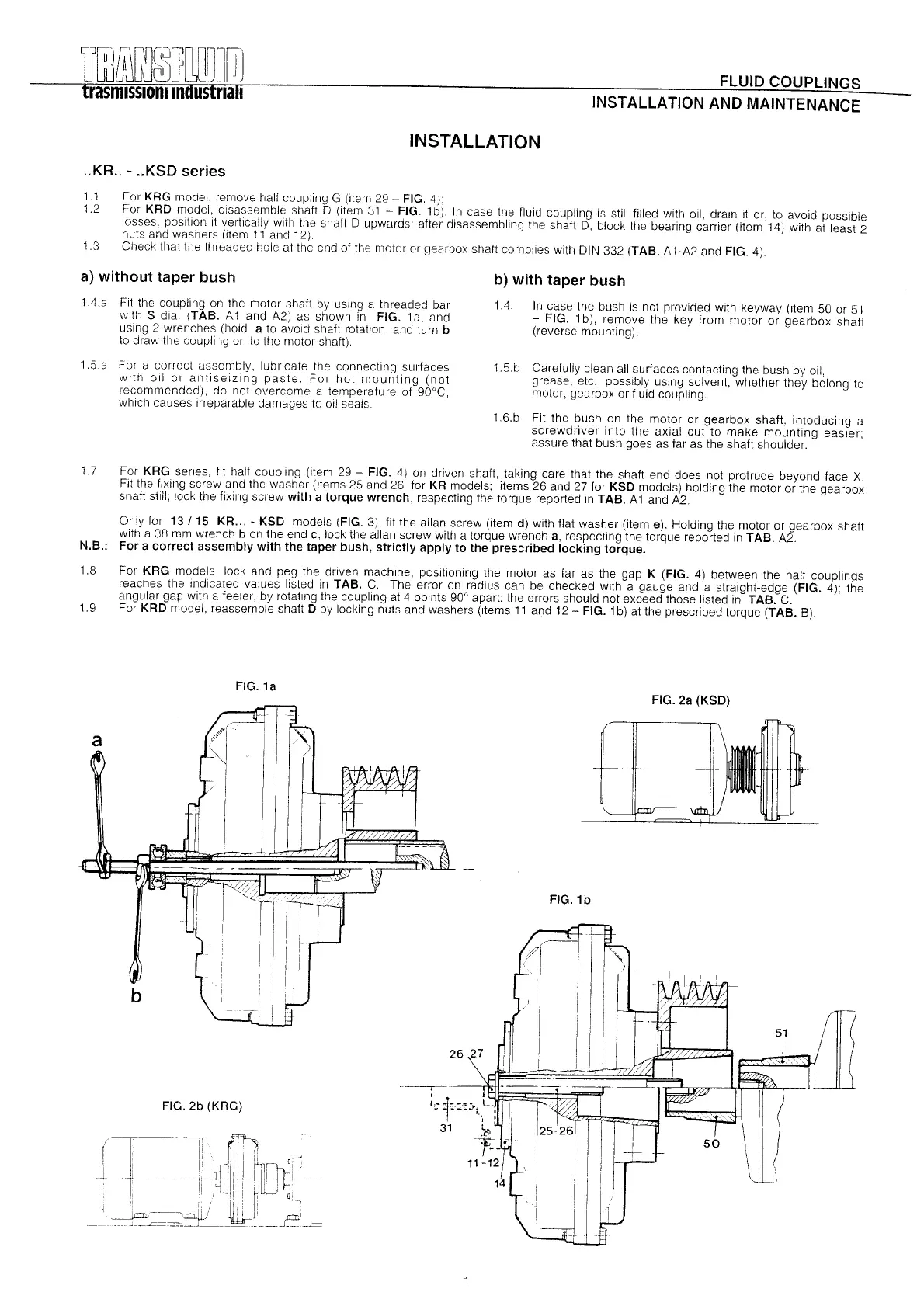
For KRD model, disassemble shaft D (item 31
-
FIG. 1b). In case fhe fluid coupling is stHI filled with oil, drain it or, to avoid possible
losses, position it vertically with lhe shalt D upwards; alter disassembling the shaft D, block the bearing carrier (item 14) with at least 2
nuts and washers (item 11 and 12),
Check that the threaded hole at the end of the motm 01'gearbox shalt complies with DIN 332 (TAB. A1-A2 and FIG. 4),
1,3
a) without taper bush
1A.a Fit the coupllng on the motor shaft by using a threaded bar
with S dia. (TAB. A 1 and A2) as shown in FIG. 1a, and
using 2 wrenches (hold a to avoid shaft rotatlon, and tum b
to draw the coupling on to the motm shalt),
1,5.a For a correcl assembly, lubricate the connecting surfaces
wlth oil 01' antiseizlng paste, For hot mouniing (not
recommended), do not overcome a temperature of 90°C,
Wllich causes Irreparable damages to oil seals,
b) with taper bush
1.4.
In case the bush is not provided with keyway (ílem 50 or 51
-
FIG. 1b), remove the key from motor or gearbox shaft
(reverse mounting).
1.5.b Carefully clean all surfaces contacting the bush by oil,
grease, etc., possibly usmg solvent, whether they belong to
motor, gearbox 01'fluid coupling.
1.6.b Fit the bush on the motor or gearbox shaft, intoducing a
screwdriver into the axial cut to make mounting easier;
assure that bush goes as far as the shaft shoulder.
For KRG series, fit half coupling (item 29
-
FIG. 4) on driven shaft, taking care that the shaft end does not protrude beyond face X.
Fit the fixing screw and the washer (items 25 and 26 for KR models; items 26 and 27 for KSD models) holding the motor or the gearbox
shaft still;
lock
the fixing screw with a torque wrench, respecting the torque reported in TAB. A 1 and A2.
Only for 13/15 KR KSD models (FIG. 3): fit the allan screw (item d) with flat washer (item e). Holding the motor or gearbox shaft
with a 38 mm wrench b 01'1the end c, lock the allan screw with a torque wrench a, respecting the torque reported in TAB. A2.
N.B.: For a correct assembly with the taper bush, strictly apply to the prescribed locking torque.
1.7
1.8
For KRG models, lock and peg the driven machine, positioning the motor as far as the gap K (FIG. 4) between the half couplings
reaches the Indicated values listed in TAB. C. The error on radius can be checked with a gauge and a straight-edge (FIG. 4): the
angular gap with a feeler, by rotating the coupling at 4 points 90° apart: the errors should not exceed those listed in TAB. C.
Fm KRD model, reassemble shaft D by locking nuts and washers (items 11 and 12 - FIG. 1b) at the prescribed torque (TAB. B).
-
I I
l;:
:h:=:>t
\_-,
I
-,
~
t
I
31 L. I
f-
I
11..12
1.9
FIG.1a
a
b
FIG. 2b (KRG)
FIG. 2a (KSD)
FIG.1b
26-27
i
¡
 Loading...