K... FIX SCREW
Steel
T orque
CK../CCK..
S
spec.
(Nm)
M6
10,9
~7-8
M8
35
M10 8,8
50
M10 10,9
70
9-11-12 M12
85
-
M16
8,8
205
13
-
15
~M20
400
KRD nu!
T
orque
CK../CCK,
11
(Nm)
7 - 8
M7
16
9 -11-12
M8
24
13
-
15
M10
50
17
-
19
21
-
24
M14
135
27
-
29
M16
205
34 CKRD
..KRG
Fluid
Dimensions in mm
coupling
K
R
A1- A2
6
02
0,2
0,3
7
-
8
10
2
~0,4
9 -11-12
20 0,35
13
BT
30
0,4
15
40
0,6
3
-
17-19
50
0,5
21
-
24
60
27 - 29
CT 80
..i.
0,8
0,6
34
CT 90
5
M12
85
9-11-12
M16
8,8
205
13
-
15
17
-
19
M20 400
21
-
24
27
-
29
M24
690
34
M36
1500
urnffiwUJ~urn~[[J
trasmlsslom Industrlall
FLUID COUPLlNGS
INST AL LA TION AND MAINTENANCE
)
FIG.4
e
e
FIG.3
29
"",
'FIXING SCREW
MISALlGNMENT
AXIAL
RADIAL
ANGULAR
a
+ 1
-
0,5
R
A1
I
'
I
I
I I
I
I I
I I
¡
I
A2
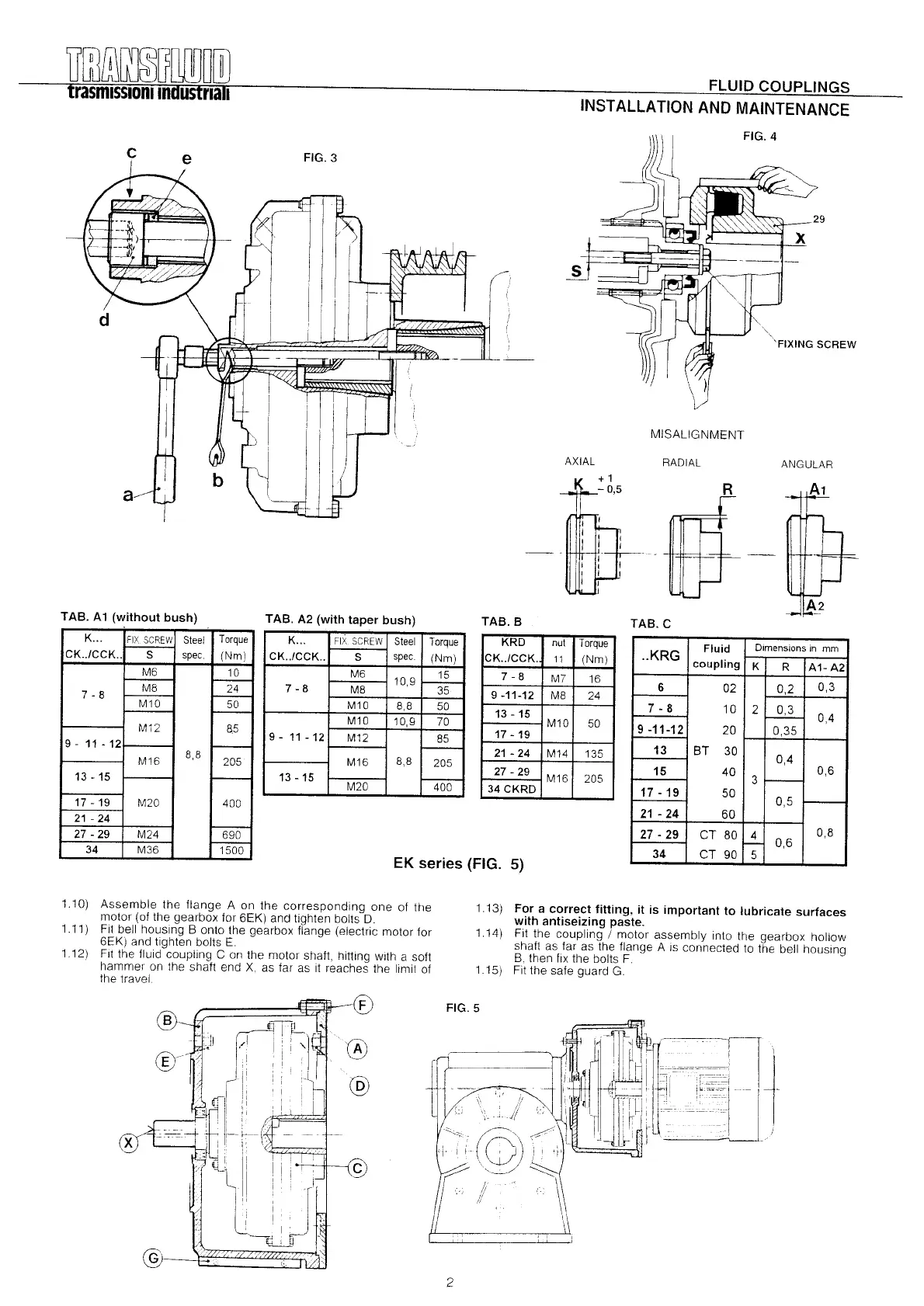
TAS. A1
(without bush)
K... FIX SCREW Steel T orque
CK..lCCK..
S
spec
(Nm)
M6 10
M8 24
M10 50
TAS. A2
(with taper bush)
TAS. S
TAS.C
7-8
EK series (FIG. 5)
1.10) Assemble the flange A on the corresponding one of the
motor (of the gearbox far 6EK) and tighten bolts D.
1.11) Fit bell housing B onto the gearbox flange (electríc motor for
6EK) and tighten bolts E.
112) Flt the fluid coupling C on the motar shaft, hittíng wlth a soft
hammer on the shaft end X, as lar as it reaches the limit 01
the travel
1.13) For a correct fitting, it is important to lubricate surfaces
with antiseizing paste.
1.14) Fít the coupling / motor assembly into the gearbox hollow
shaft as lar as the Ilange A is connecled lo the bell housíng
B. then lix the bolts F.
1.15) Fit the sale guard G.
CD
FIG.5
:§)
@
@
@
2
 Loading...