TAB.D2
OIL QUANTITY (11.)
CK... 2 3
4
11
3.350
3.050 2.750
12
4.800 4.200 3.600
13
5.800 5.200 4.700
15
8.600
7.700 6 AOO
17
13.60 12.80
1170
19
16.50
15.20 14.00
21
2300 21.30
1930
24
31.20
28.60 26.00
27
50.00
46.50 43.00
29
6300 59.00
54.00
34
92.50
88.50
83.50
TAB. D1
OIL QUAI'HlTY
(11.)
K... X 1 2
3 4
6
0.505 OA80 OA55
OA25 0.390
7
0.920
0.860 0.800 0730 0.650
8
1.510
1A05
1.295 1.190 1.080
9
1.950
1.820 1.690 1.550
1AOO
11
2.750
2.550 2.350
2.100 1.850
12
4100
3.875 3.575
3.250 2.900
13
5.200 4.850
4A50 4.050
3.600
15
7650
7.150 6600 6.000 5AOO
17
11.70 10.90
10.00 9.100
8.200
19
14.20
13.30 12.30
11.20 10.00
21
19.00
17.80
16AO 15.00
1350
24
28 AO
26.50
2460 22.60
20.50
27
42.00
39.00 36.00
33.50
31.50
29
55.00 51 00
47.00 44.00
41.50
34 82.50
76.60
70.60
66.20
62.50
TAB.D3
OIL QUANTITY (11.1
CCK...
3
4
15
9.30
8.00
17
16.36
14.86
19
18.76 16.86
21
2730
24.30
24
35A3 31.63
27
59.35 55.15
29
70.60 65.20
34 96.70
86 AO
SIZE
CUSIBLE PLUG
O.nolT]
l. ,C,;?TorquE- iNmj
6 hb
12
1/2'
7
-
8
-
9
88
23
í/4
11
12
13
-
15
17-
19
ceo 29
31e'
21
,24
27
-
29
8E::
44
34
TIrnffiw~üllillu[]
trasmlsslom mdustnall
2. FLUID COUPLlNGS FILLlNG INSTRUCTIONS
KR... - KSD - EK SERIES
TI'ansfluld fluld coupllngs are no! supplled wlth 011
Therelore 11IS necessary to achleve the lollowlng pracedure:
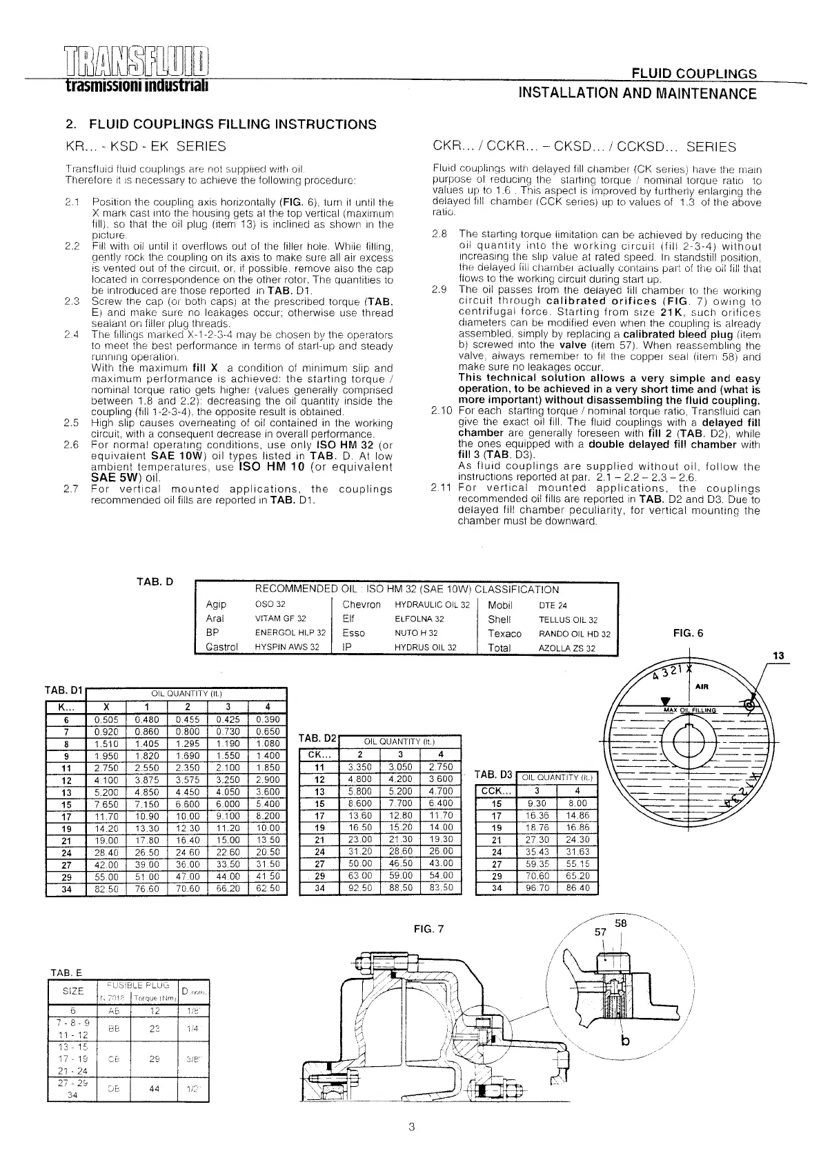
2.1 Positlon the coupllng axls horizontally (FIG. 6). turn I1until the
X mark cast Into the houslng gets al tlle top vertical (maxlmum
fill). so that tlle 011plug (item 13) Is Inclined as shown III the
plcture
FIII wlth 011untll it overflows out 01 the filler hole. Whlle fllllng,
gently rack the coupllng on its axls to make sure all air excess
IS vented out of the clrcult, 01', If posslble. remove also tlle cap
located In correspondence on the other rotor. The quantltles to
be Intraduced are those reported in TAB. 01.
Screw the cap (or both caps) at the prescribed torque (TAB.
E) and make sure no leakages occur; otherwise use thread
sealant on filler plug tllreads.
The líllings marked X-1-2-3-4 may be chosen by the opel'ators
to meet the be sI performance In terms 01 start-up and steady
runnlng operatíon.
With the maxlmum fill X a conditlon 01 mlnlmum slip and
maxlmum performance Is achieved: the startlng torque !
nominal torque ratlo gets higher (values generally comprised
between 1.8 and 2.2) decreaslng the 011quantlty Inslde the
coupling (fII11-2-3-4), the opposite result Is obtained.
HIgh slip causes overheating of 011contalned in the worklng
circuit, wlth a consequent decrease IIIoverall performance.
For normal operatlng conditions, use only ISO HM 32 (01'
equivalent SAE 10W) 011 types listed in TAB. O. At low
amblent temperatures, use ISO HM 10 (01' equivalen!
SAE 5W) ol!.
For vertical mounted appllcatlons, the coupllngs
recommended 011fllls are reported in TAB. 01.
22
2.3
24
2.5
2.6
27
TAB.D
FLUJD COUPLlNGS
INST ALLA TION
AND MAINTENANCE
CKR... / CCKR... - CKSD... / CCKSD... SERIES
Fluid couplillgS Wltll delayed IIIIchambel (CK series) have the mal n
purpose ot reduclng tlle startíng torque / nominal torque ratlo to
values up to 1.6 . Thls aspecl Is Improved by furtherly enlarglng the
delayed flll chambel (CCK series) up to values of 1.3 of the above
ratío
2.8 The startíng torque Ilmítatlon can be achieved by reducíng the
oil quantlty ínto the worklng clrcult (till 2-3-4) without
IIlcreaslng the slip value a! rated speed. In standstill positlon,
the delayed lill chambel actually COlltalllS par! 01 the oil II11that
Ilows to the working clrcuit durlng start up.
2.9 The 011 passes Irom the delayed IIII chamber to the workíng
clrcuit tllrough calibrated orifices (FIG. 7) oWlng to
centnlugal lorce. Starting Irom slze 21 K, such orillces
dlameters can be modílied even when the coupllng is already
assembled, slmply by replacing a calibrated bleed plug (item
b) screwed IIlto the valve (Item 57). When reassembling the
valve, always remember to flt the copper seal (Item 58) and
make sure no leakages occur.
This technical solution allows a very simple and easy
operation, to be achieved in a very short time and (what is
more important) without disassembling the fluid coupling.
210 For each starting torque ! nominal torque ratío, Transfluld can
give the exact oíl lill. The Iluíd coupllngs with a delayed fill
chamber are generally foreseen with fill 2 (TAB. 02), while
the ones equlpped wlth a double delayed fill chamber with
fill 3 (TAB. 03).
As fluid couplings are supplied without 011, lollow the
instructlons reported at par. 2.1 - 2.2 - 2.3
-
2.6.
211 For vertical mounted appllcatlons, the coupllngs
recommended oíl fills are reported In TAB. 02 and 03. Oue to
delayed lill chamber peculiarity, for vertical mounting the
chamber must be downward.
Aglp
Aral
BP
Castrol
RECOMMENDED OIL ISO HM 32 (SAE 10W) CLASSIFICATION
OSO 32 Chevron HYDRAULlC OIL 32 Mobil DTE 24
VITAM GF 32 El! ELFOLNA 32 Shell TELLUS OIL 32
ENERGOL HLP 32 Esso NUTO H 32 T exaco RANDO OIL HD 32
HYSPIN AWS 32 IP HYDRUS OIL 32 Total AZOLLA zs 32
FIG.6
~~.,.,
1/
.
/
~
/
..
57\.
...
:
.......
I
....
"',
(
"
",
~..-\
..
.~ \ .
:
I \
\
/
~// b
rl~
~
l
.
'"
...
:I~
.
~
..
¡
J
{1/
,
,
~
FIG.7
TAB.E
/
-,~.-
3
 Loading...