:z:
o
o
w o..
¡:::
o
w
:::o
« «
o..
I
Dé
o
UJ
>-
W
-'
FIG.13
Dé
o..
Dé
«
o
w
>-
>
UJ
o
ITrnmwg)Uilllfl~rn
trasmlsslom Industrlall
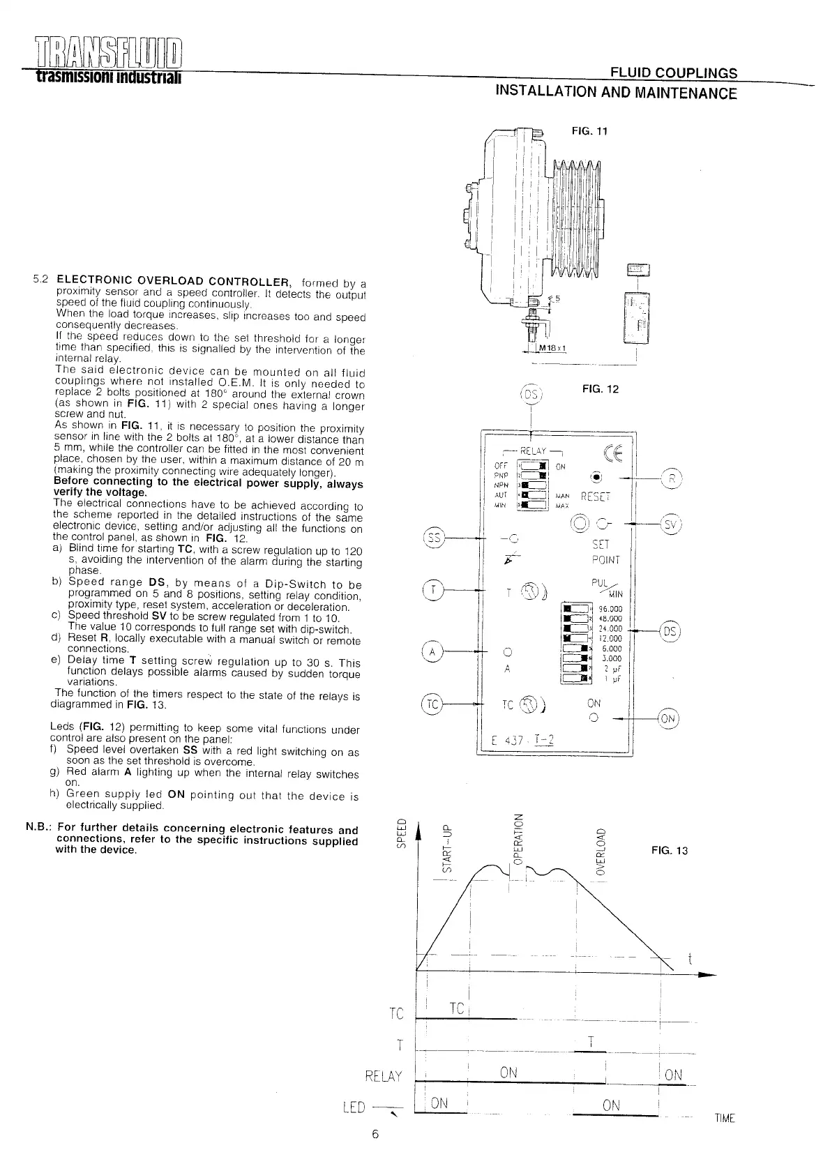
5.2 ELECTRONIC OVERLOAD CONTROLLER, formed by a
proximity sensor and a speed controller. It detects the output
speed of the fluid coupling continuously.
When the load torque increases, slip increases too and speed
consequently decreases.
II the speed reduces down to the set threshold far a longer
time than specified, thls is signalled by the intervention 01 the
internal relay.
The said electronic device can be mounted on all fluid
couplings where not installed O.E.M. It is only needed to
replace 2 bolts positioned at 180' around the external crown
(as shown in FIG. 11) with 2 special ones having a longer
screw and nut.
As shown in FIG. 11, it is necessary to position the proximity
sensor in line with the 2 bolts at 180°, at a lower distance than
5 mm, while the controller can be fitted in the most convenient
place, chosen by the user, within a maximum distance of 20 m
(making the proximity connecting wire adequately longer).
Before connecting to the electrical power supply, always
verify the voltage.
The electrical connections have to be achleved according to
the scheme reported in the detailed instructions 01 the same
electronic device, setting and/or adjusting all the functions on
the control panel, as shown In FIG. 12.
a) Blind time lor starting TC, wlth a screw regulation up to 120
s, avoiding the intervention of the alarm during the starting
phase.
b) Speed range DS, by means 01 a Dip-Switch to be
programmed on 5 and 8 positions, setting relay condition,
proximity type, reset system, acceleration or deceleration.
c) Speed threshold SV to be screw regulated from 1 to 10.
The value 10 corresponds to full range set with dip-switch.
d) Reset R, locally executable with a manual switch or remote
connections.
e) Delay time T setting screw regulation up to 30 s. This
lunction delays possible alarms caused by sudden torque
variations.
The lunction of the timers respect to the state of the relays is
diagrammed in FIG. 13.
Leds (FIG. 12) permitting to keep some vital lunctions under
control are al so present on the panel:
1) Speed level overtaken SS with a red light switching on as
soon as the set threshold is overcome.
g)
Red alarm A lighting up when the internal relay switch es
on.
h) Green supply led ON pointing out that the device is
electrically supplied.
N.B.: For further details concerning electronic features and
connections, refer to the specific instructions supplied
with the device.
LED~
6
RELAY
FLUID COUPLlNGS
INST ALLA TION AND MAINTENANCE
FIG.11
~
¿I
:1
f'l
--~~~----
11
11
,1
l'
11
11
I~'
I!
I¿Y-~
:1
/-.
1:OS)
--.,/
I
I
f
~.
REL4Y-,
OFF
1" -IoN
PNP ¡,c=JIi
NPN
!J-=:J!
AUT
l'
a::=J!
\AAN
MIN
1).':" ~I
\AAX
(E 1]
'.' ~~\
RE~~T
I1
'~I
~ I1 /~
1,--/1-
~\,.:~~:/)
SET
POINT
FIG.12
-(=¡
T
- (D:'i\
1
'.:Y
j)
P%
MIN
IIL H 96000
I
-=:J'I
48.000
-=:J,I
24.000
rr--<DS)
..:=J,¡
12.000 .'-.,./
,c=JI~ 6.000
1
: =::~
3000
c=JI'
2 ~F
ic:JI I ~F
(]
A
@
11
[!4CJ~i)¡
ON
(]
,~
ON)
''-.,./
TC
TIME
T
T
I
--------
~--~------
ON ION
ON
 Loading...