GASKET KIT
FUSIBLE PLUG
RUBBER
SIZE
1186
1535
N 7018
BLOCK
K...
CK... CCK..
120"C
145"C Std
175"C
W
CODE
6
AV
AA
AB
AC
8
BT-A
7
BV
I
BT-S
8 CV
-
9
DV
SA
SS
SC
12
11
EV
ST-C
12KR FV
BV
12KSD
GV
CV
-
13
HV OV
ST-C
15 KV
EV
17
LV FV
CA CS
CC
ST-D
19
MV
GV
21
NV
HV
16
SToP
24
OV
KV
27KR QV
LV
CT-D/E350
29KR
RV MV
DA OB
DC
34KR SV
NV
CT-D/E425
K...
LOCKING TORQUE
CK...
Item 9
Item 10 ¡tem 34
CCK...
screw
Nm
screw
Nm
screwl Nm
6
M5
6
M6
10
--
7-8
M6
10
9 - 11
M8
24 M8
24 M8
24
12-13
15-17-19
M10 50
M10
50
21
M12
85
M10
50
24
M14
135
M14
135
27
29
M16
205
M14
135
34
M16
205
M20
400
TIrnffiw[B~[illJ~rn
trasmlsslom Industrlall
FLUID COUPLlNGS
INST ALLA TION AND MAINTENANCE
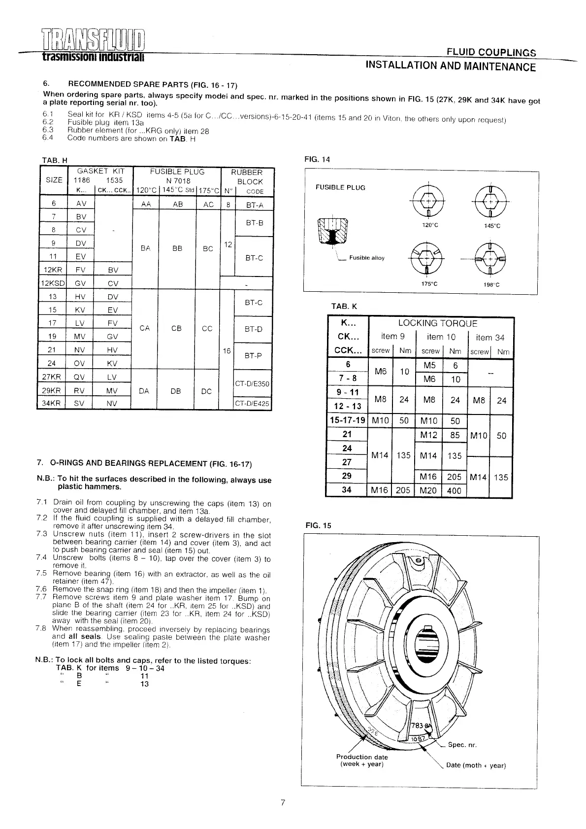
6. RECOMMENOEO SPARE PARTS (FIG. 16 -17)
When ordering spare parts. always specity modei and spec. nr. marked in the positions shown in FIG. 15 (27K, 29K and 34K have got
a plate reporting serial nr. too).
6.1 Seal kit lor KR / KSD items 4-5 (5a lar C ICC. versions)-6-15-20-41 (Items 15 and 20 In Viton, the others only upon request)
6.2 Fusible plug item 13a
6.3 Rubber element (lor ...KRG only) Item 28
6.4 Code numbers are shown on TAB. H
TAB H
7. O-RINGS ANO BEARINGSREPLACEMENT (FIG. 16-17)
N.B.: To hit the surtaces described in the tollowing, always use
plastic hammers.
7.1 Drain 011Irom coupling by unscrewlng the caps (Item 13) on
cover and delayed II11chamber, and Item 13a.
7.2 1I the Iluid coupllng Is supplled wlth a delayed 1111chamber,
remove it alter unscrewing item 34.
7.3 Unscrew nuts (Item 11), Insert 2 screw-drlvers in the slot
between bearlng carrier (item 14) and cover (Item 3), and act
to push bearing carrier and seal (item 15) out.
7.4 Unscrew bolts (Items 8
-
10), tap over the cover (item 3) to
remove It.
7.5 Remove bearing (item 16) wlth an extractor, as well as the 011
retalner (Item 47).
7.6 Remove the snap rlng (Item 18) and then the impeller (item 1).
7.7 Remove screws item 9 and plate washer Item 17. Bump on
plane B 01 the shalt (item 24 lor ..KR, Item 25 lar ..KSO) and
sllde the bearlng carrier (Item 23 lor ..KR, Item 24 lar ..KSD)
away wlth the seal (Item 20).
7.8 When reassembllng, proceed Inversely by replaclng bearlngs
and all seals. Use sealing paste between the plate washer
(Item 17) and the impeller (Item 2).
N.B.: To lock al! bolts and caps, reter to the listed torques:
TAB. K tor items 9 - 10 - 34
B 11
E 13
FIG.14
FUSIBLE PLUG
@@
.
I
120'C
145'C
@@
\---
Fusible alloy
175'C
198'C
TAB.K
FIG.15
Date (moth . year)
7
 Loading...