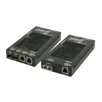
CFETF10xx-205
2
Tech Support: 1-800-260-1312 Int’l: 00-1-952-941-7600 7am-6pm CST (GMT-6:00)
INSTALLATION
CAUTION: Wear a grounding device and observe electrostatic discharge
precautions when setting the 4-position switch and the jumpers and when
installing the Slide-in-Module Media Converter. Failure to observe this caution
could result in damage to, and subsequent failure of, the Media Converter.
Set the 4-Position Switch
The 4-position switch is located on the
Media Converter circuit board. Use a
small flatblade screwdriver or a similar
device to set the recessed switches.
Refer to the drawing to the right for the
locations of the four individual switches.
1. Full- / Half-Duplex
UP Advertises 100 Mb/s Full-Duplex (only during Auto-Negotiation).
(See page 5.)
DOWN Operates at 100 Mb/s in Half-Duplex mode of the attached
device. (Used primarily when connecting to a hub).
2. Pause
(Applies ONLY if switch 1 is UP (Full-Duplex) AND the Media Converter is
connected to Auto-Negotiation device(s) capable of Pause Control Frame.)
UP Allows negotiation of Pause Control Frame. (See page 6.)
DOWN Does not allow negotiation of Pause Control Frame.
3. Link Pass-Through
UP Enables Link Pass-Through. (See page 6.)
DOWN Disables Link Pass-Through.
4. Far-End Fault
UP Enables Far-End Fault. (See page 6.)
DOWN Disables Far-End Fault.
Set the Hardware/Software Jumper
The jumper is located on the Media Converter circuit board and is labeled
“H” and “S”. Use small needle-nosed pliers or a similar device to set the
jumper. Refer to the drawings below when setting the Media Converter for
hardware or software mode.
Hardware The Media Converter mode is determined
by the 4-position switch settings listed
above.
Software The Media Converter mode is determined
by the most-recently saved, on-board
microprocessor settings.
Software Mode
Hardware Mode
H
S
H
S
Not Used
Link Pass-Through (UP=Enable)
AutoCross (UP=Enable)
Full/Half-Duplex (UP=Full)
1234
techsupport@transition.com -- Select the “Transition Now” Link for a Live Web Chat
3
INSTALLATION -- Continued
Set the AutoCross™ Jumper
The AutoCross™ jumper is located on the Media Converter circuit board and
is labeled “D” and “E”. Use small needle-nosed pliers or a similar device to
set the jumper. Refer to the drawings below when setting the AutoCross™
feature on the Media Converter.
Disable Either straight-through or crossover
twisted-pair copper cable must be
installed, according to the site
requirements.
Enable The Media Converter connects
automatically to either straight-through or
crossover twisted-pair copper cable.
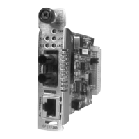
Install the Slide-In-Module
CAUTION: Wear a grounding device and observe electrostatic discharge
precautions when installing the CFETF10xx-205 Slide-in-Module Media
Converter. Failure to observe this caution could result in damage to, and
subsequent failure of, the Media Converter.
1. Carefully slide the Slide-in-Module into the installation slot, aligning the
Slide-in-Module with the installation guides.
2. Ensure that the Slide-in-Module is firmly seated against the back of the
chassis.
3. Secure the Slide-in-Module by securing the panel fastener screw
(attached to the Slide-in-Module) to the chassis front.
CFMFF100
CFMFF100
CETCF100
CFETF100
CFETF110
CFMFF100
SPD
PWR
FRX
CRX
FLNK
CLNK
10/100TX
RX
TX
10/100SX
100BASE-TX
RX
TX
100BASE-FX
Link Alert
E
D
0
50½
LA
PWR
RXF
RXC
LNK
COL
LKS
PWR
LKM
10BASE-2
10BASE-FL
LKS
PWR
LKM
LKS
PWR
LKM
Multimode
Singlemode
TX
RX
TX
RX
Multimode
Singlemode
TX
RX
TX
RX
Multimode
Singlemode
TX
RX
TX
RX
I
0
TERM
INIT
RX
TX
LNK
PWR
CPSMM120
SERIAL
10BASE-T
R
E
S
E
T
I
0
100BASE-TX
RX
TX
100BASE-FX
Panel Fastener Screw
PWR
RXF
LKF
RXC
LKC
Disable Autocross
Enable Autocross
DE
DE
 Loading...