0314
3
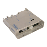
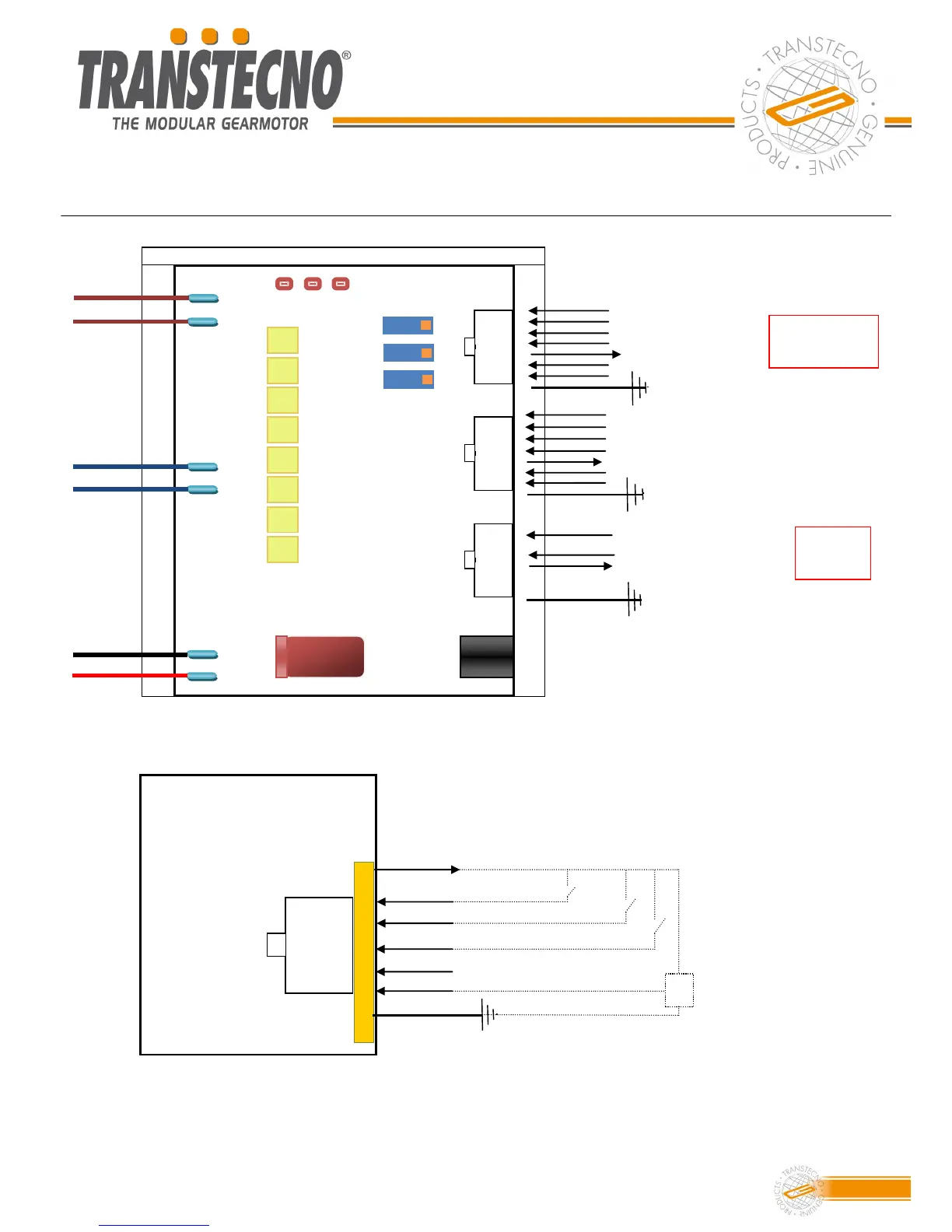
Motor cables
Cavi motore
POWER+
POWER-
MOTOR+
MOTOR-
BRAKE+
BRAKE-
CN1
CN2
CN3
TR3
TR2
TR1
LD1 LD2 LD3
1
1
1
8
8
8
5
Massa encoder / Encoder ground
2
4
5
6
7
Ingresso digitale / Digital input
Ingresso marcia indietro / RUN Reverse
2
6
7
3
2
3
4
5
6
7
Ingresso digitale reset / Reset
3
4
Canale A+ / Channel B+
Canale B+ / Channel B+
OUT 3-
OUT 1+
+V
OUT 3+
OUT 2-
OUT 2+
OUT 1 -
1
4
5
8
2
3
7
6
1
4
5
8
2
3
7
6
1
4
5
8
2
3
7
6
Ingresso marcia avanti / RUN Forward
Vedere a pag 4
See at pag. 4
Alimentazione encoder 5Vcc /
Encoder Supply 5Vdc
Ingresso potenziometro o segnale 0-10Vcc / Speed pot input or 0-10Vdc signal
Connection diagram
Diagramma dei collegamenti
CN2
1
6
2
4
7
3
8
Ingresso potenziometro o segnale 0-10Vcc /
Speed pot input or external analog signal
Ingresso reset / Reset
Ingresso marcia avanti / RUN Forward
Ingresso marcia indietro / RUN Reverse
Alimentazione 10 Vcc, potenziometro e comandi /
10 Vdc, supply voltage for speed pot and commands
Potenziometro
5-10 kOHM
Speed pot 5-10
kOHM
1
4
5
8
2
3
7
6
Ingresso digitale / Digital input
Dettaglio connettore CN2 / Details of Connector CN2
Pin 5: ingresso ausiliario analogico (solo versione Option) / Pin 5: auxiliary analogue input (only
option version)
Pin 6 non utilizzato. Pin n° 6 non used.
Ingresso analogico ausiliare (solo option) / Analog input (only option)
Alimentazione 10 Vcc, potenziometro e comandi/10 Vdc supply for seed pot and commands
SOLO Option
ONLY Option