ENGLISH
26
www.trapp.com.br
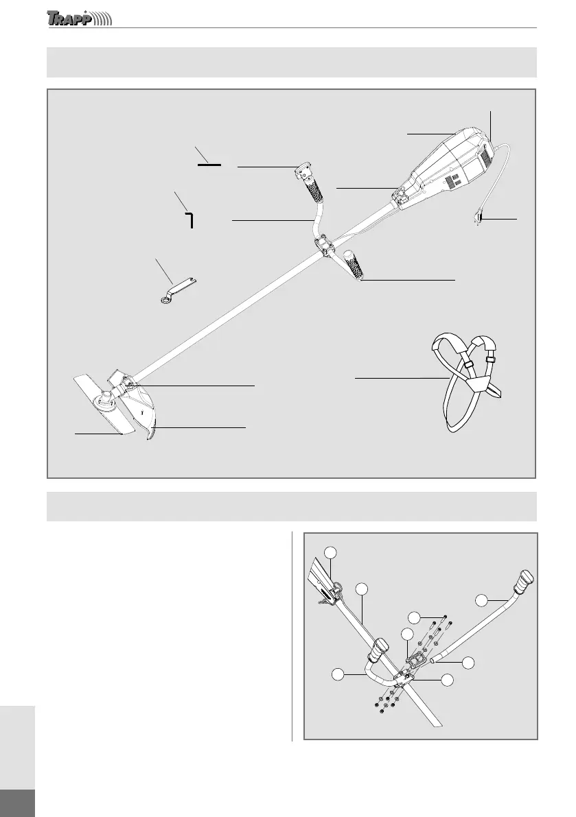
Main Components
Pino para
travamento
da lâmina
Chave Allen
(5 mm)
Chave fixação
da lâmina
Caixa de
transmissão
Lâmina
Saia de
proteção
Cinto de
sustentação
Guidão esquerdo
Plugue
Guidão direito
Chave
liga/desliga
Engate do
cinto de
sustentação
Corpo
do motor
Blade
locking pin
Allen
wrench
(5 mm)
ON/OFF
Switch
Blade fixation
wrench
Protection
device
Blade
Transmission
box
Left handlebar
Support belt
coupling
Engine
body
Voltage
selector
Right handlebar
Plug
Support belt
Master 3000
Image merely illustrative
Pino para
travamento
da lâmina
Chave Allen
(5 mm)
Chave fixação
da lâmina
Caixa de
transmissão
Lâmina
Saia de
proteção
Cinto de
sustentação
Guidão esquerdo
Plugue
Guidão direito
Chave
liga/desliga
Engate do
cinto de
sustentação
Corpo
do motor
Assembling the Handlebars
With the machine safely supported, release the
four screws (2) and move away the handle bar
clip (3), fix the right handle bar (6), observing
the bore (8) that shall fix in the pin existing in the
handlebar support (5). Place the power supply cord
(4) according to the next figure, approximate the
clip (3) and slightly fasten both screws on this side.
Next, fix the left handlebar (1) on the other side,
also observing the fitting bore and slightly fasten
the respective screws. Only then completely fasten
both sides. Finally, with the brush cutter placed in
the support belt in working position, measure the
distance between the handlebar support (5) and
the engine body (7), according to most comfortable
position for the work.
Image merely illustrative
7
4
1
8
5
6
3
2