8 VSD2H Variable Speed Drives Data Sheet TA201104 Issue 3, 08-Oct-2013
VSD2H Data Sheet
INSTALLATION
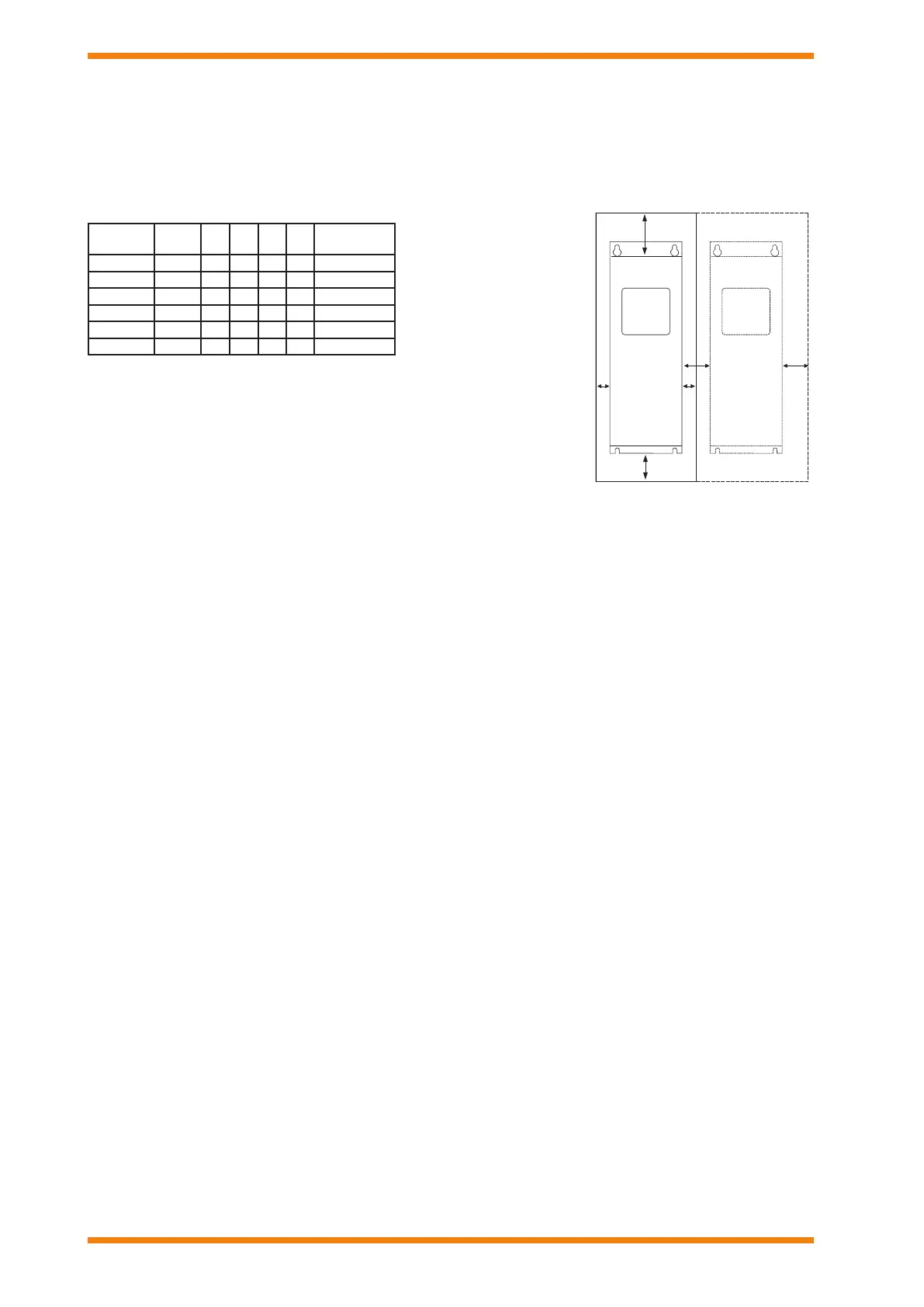
CLEARANCES
The Trend VSD2H drive must be installed in a vertical position. It can be mounted on a wall or in an enclosure using four screws or
bolts. The cooling airow to the drive must not be blocked in any way, recirculation of air inside the enclosure should be avoided.
Different acts of maintenance also require certain amount of free space.
Make sure that the temperature of the cooling air does not exceed the maximum ambient temperature of the converter.
Key:
A: clearance around the freq. converter (see also B)
B: distance between two drives or distance to cabinet wall
C: free space above drive
D: free space below drive
If several units are mounted above each other the required space between them equals C+D. Also the outlet air used for cooling the
lower unit must be directed away from the inlet air to be used by the upper unit.
INSTALLATION PROCEDURE
Overload protection of the supply cable should be considered (e.g. fuses). The use of shielded motor cables is recommended; they
should be routed as far away from other cables as possible, and cross other cables at right angles. The motor cable shield should
be grounded at both the VSD2H drive and at the motor.
The installation involves:
mount the controller in position
connect mains cable
connect motor cable
check mains and motor cable insulation
connect control cable
check quality and quantity of cooling air
check inside of drive for condensation
set up DIP switches
check all start/stop switches connected to I/O are at stop
switch on power to drive
congure the drive (e.g. using the keypad)
perform run test without motor
commission with motor connected
This installation procedure, is covered by the Trend VSD2H Installation Manual, TE201102.
MODBUS installation is covered by the MODBUS Protocol Installation and User’s Manual TE201235
BACnet installation is covered by the BACnet Protocol Installation and User’s Manual TE201234
Current (A) Frame *A *B C D
Cooling Air
Required m
3
/h
3 to 12 MR4 20 20 100 50 45
16 to 31 MR5 20 20 120 60 75
38 to 61 MR6 20 20 160 80 190
72 to 105 MR7 20 20 250 100 185
140 to 205 MR8 20 20 300 150 335
261 to 310 MR9 20 20 350 200 621
* Minimum clearances A and B
for drives with IP54 enclosure
is 0 mm
 Loading...