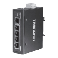
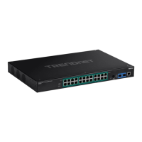
Front View
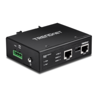
Rear View
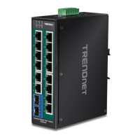
• LED Indicators – Indicators on the left display ALM, PWR, and POST status.
LEDs on each port show the status of the port based on the mode selected
using the Mode Button.
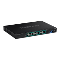
• Mode Button (TI-RP262i only) – Press the mode button to change the left LED
indicator on each port to display Speed, or PoE Mode. When button is
depressed it will display PoE, when not pressed it will indicate if 1000Mbps.
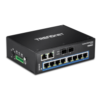
• Gigabit Ethernet PoE+ Ports (1-24) – Connect either network PoE+ or non-PoE
devices.
• Reset Button – Press and hold the button for less than 5 seconds to reboot, or
more than 5 seconds to reset to factory default.
• SFP Slots (25-26) – Supports optional 1000BASE-SX/LX mini-GBIC modules for
uplink or downlink connections.
• Console Port – The console port is a female RJ-45, use the included RJ-45 male
to RS-232 serial DB-9 female console cable.
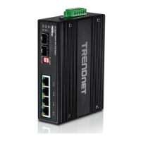
• Power Terminals – Using proper gauge wire, terminate the leads from your
power supply to these power terminals to power your switch.
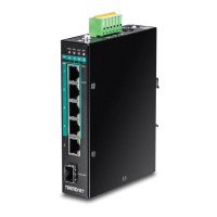
LED Indicators
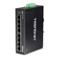
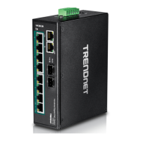
• Ports 1-4 – Designed to operate at 10Mbps, 100Mbps, or Gigabit speed in both
half-duplex and full-duplex transfer modes. Supports Auto MDI-X and capable
of delivering up to 30W (802.3at PoE+) per port.
• Port 5 - Designed to operate at 10Mbps, 100Mbps, or Gigabit speed in both
half-duplex and full-duplex transfer modes. Supports Auto MDI-X
• SFP Slot 6 – Designed to operate at Gigabit speeds.
• Reset/Reboot Button – Push the button for 10 seconds and release to reset the
switch to factory defaults. Push the button for 3 seconds and release to reboot.
• Grounding point/screw – The switch chassis can also be connected to a known
ground point for additional safety and protection. (grounding wire not
included)
Note: For any unused ports or SFP slots, it is recommended to leave the rubber plugs
installed during operation.
 Loading...