WALL INSTALLATION
8
1) Add sand.
2) Choose the filter location beside a round section (never in a
straight section). The starting point should be at that location where
the skimmer and return holes are, and as close as possible to the
filtration system.
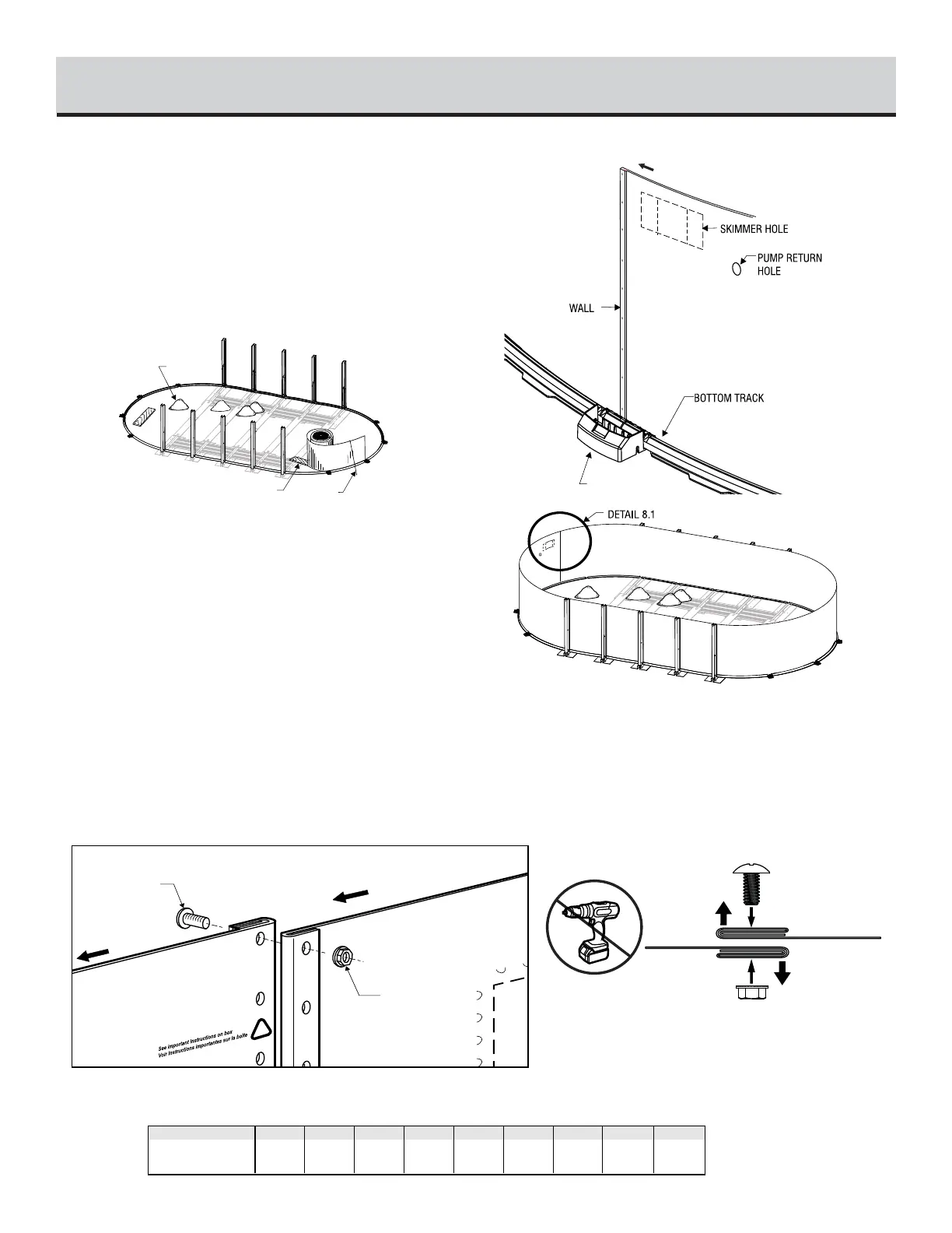
3) Before uncoiling the wall, make sure the pre-punched holes for
the skimmer and pump return are at the top and facing the planned
location of your filter.
Begin inserting the wall into the bottom tracks in the middle of a
bottom plate. At first, the wall is kept in place with one or two stakes
and strings (or extra persons). One person uncoils the wall on a
beam or a plank, while a second person inserts it in the bottom
tracks. Do not uncoil more than 3 m (10') of wall before you install
a support bar or stake and string to reinforce the structure.
Once the wall is completely uncoiled, you may find that it is too
long or that both ends do not meet by a few centimetres. If such is
the case, adjust tracks and bottom plates until wall holes line up. If
this does not work, roll up the wall again, check measurements as
per Illustrition 1.1, adjust tracks and plates, if applicable, and uncoil
the wall again. If the spread is too wide, measure the wall and check
it against the chart below.
Join both ends of the wall by orienting folds outward to hide the ex-
clamation icon. (Illustration 8.1)
Note: If the wall is attached properly, you should no longer see
the exclamation icon. If you can always see the icon, you must
reverse the overlap.
Insert bolts and nuts in every hole and tighten with wrench (screw
head on water side of wall). Tape over screw heads with duck tape.
Chart
Illustration 8.1
IMPORTANT! Installing the wall joint in non-compliance with the specifications dictated by the manufacturer will void the warranty.
faulty installation will cause the wall/joint to split which could result in serious and/or fatal injuries!
MODELS 10x16 18x33
ACTUAL LENGHT
OF THE WALL
10x19 10x22 12x18 12x24 15x24 15x30
43' 8" 49' 8" 55' 9" 49' 8 1/2" 61' 9 3/8" 77' 2 1/2" 86' 7 1/2"
(13,30m) (15,14m) (17,00m) (15,16m) (18,83m) (19,88m) (23,53m) (26,40m)
65' 2 1/2"
12x21
55' 9 3/8"
(17,00m)
 Loading...