EasyManua.ls Logo

Trevi 106 User Manual

Trevi 106
10 pages
Go to English
To Next Page IconTo Next Page
Page #1 background imageLoading...
Page #1 background image
Choisissez l'emplacement idéal en tenant compte des
lois municipales quant à la distance des clôtures et de
c
elles des services publiques relatives à la distance
des fils électriques, ainsi que de l'aménagement
paysager qui suivra l'installation de la piscine.
Plantez un pieu au centre de l'emplacement, et à l'aide
d'un ruban à mesurer, tracez un cercle dont le rayon est
d
e 15 cm à 20 cm (6" à 8") de plus que celui du diamètre
de la paroi. (voir Illustration 1.1)
Enlevez la pelouse sur toute la surface délimitée par le
c
ercle que vous venez de tracer.
Assurez-vous de commander la quantité de sable et de
poussière de roche nécessaire. (Voir Tableau)
Cher(e) client(e),
Félicitations, vous avez fait l'acquisition d'une piscine d'une qualité et d'une durabilité
supérieures. Suivez les instructions attentivement pour obtenir les meilleurs résultats possibles.
Toute dérogation à la marche à suivre peut occasionner des dommages à votre piscine ou votre pro-
priété et annuler votre garantie. Nous vous suggérons de lire attentivement les instructions au préal-
able, afin de vous familiariser avec les différentes pièces de votre piscine. Assurez-vous de bien
c
omprendre toutes les étapes avant de commencer l'assemblage.
Nous vous souhaitons un été des plus agréable et rafraîchissant
.
A
VERTISSEMENT : Assurez-vous d’avoir lu le manuel “ Information de Sécurité
avant de commencer l’installation de votre piscine.
AVERTISSEMENT : Votre piscine n'est pas conçue pour le plongeon et/ou les
sauts tête première. Pour votre sécurité ne pas plonger.
Plonger peut causer de graves blessures ou la mort.
PRÉPARATION DE L’EMPLACEMENT
1
NIVELLEMENT DU TERRAIN
2
INSTRUCTIONS D’ASSEMBLAGE
P
ISCINE RONDE
T
revi 106 / Trevi 186 / Trevi 206 /
Trevi 217 / Trevi 218
9,14 m (30’)
4,77 m (15’8’’)
9
,54 m (31’4’’)
2
1/2 tonnes
2 tonnes
* Si vous n’utilisez que du sable, additionnez le tonnage de la poussière de roche à celui du sable.
T
ableau
Illustration 1.1
Vous devez ensuite niveler le contour du cercle, à partir de
la limite de déterrement jusqu'à 30 cm (12") à l'intérieur du
cercle.
Pour ce faire, utilisez un niveau de menuisier posé sur un
grand madrier, un niveau à corde ou un niveau optique.
Compactez bien la terre à l'aide d'un pilon ou d'une plaque
vibrante (voir Illustrations 2.1 et 2.2) surtout aux endroits
vous avez dû ajouter beaucoup de terre.
Il est également fortement recommandé de raffermir le
contour au moyen d'une couche de poussière de roche
(ou de sable) d'environ 2 cm (3/4").
Le centre du cercle pourra par la suite être creusé à la pro-
fondeur désirée (facultatif) n'excédant pas 15 cm (6")
pour une toile standard (voir Illustration 2.3).
Retirez les cailloux, les bouts de bois et autres débris qui
se trouvent à l'intérieur du cercle. Éliminez toutes les
petites buttes et tassez bien la terre. Étendez du sel pour
empêcher la repousse des racines et éloigner les vers de
terre, qui sont cause de crevasses post-installation. Éten-
dez également de l'insecticide à fourmis, autre cause de
crevasses.
Ajoutez une mince couche de 2 cm (3/4") de sable à com-
pactage afin de protéger la toile.
Assurez-vous d'entrer la quantité suffisante de sable pour
la finition du fond.
27’-0’’ DIAM. Plat : 3’-6’’
30’-0’’ DIAM. Plat : 3’-6’’
Illustration 2.3
Question and Answer IconNeed help?

Do you have a question about the Trevi 106 and is the answer not in the manual?

Trevi 106 Specifications

General IconGeneral
TypeAbove Ground
ShapeRound
MaterialSteel
Diameter3.05 m
Height0.76 m
Water Capacity5, 300 L

Summary

SITE PREPARATION

Select Pool Site

Consider municipal laws regarding fences, utilities, and landscaping.

Draw Installation Circle

Use stake and tape to draw a circle larger than the pool diameter.

Remove Turf and Order Materials

Clear grass from the circle and order necessary sand and stone dust.

SITE LEVELLING

Level Circle Edge

Level the area from the turf removal line to 30 cm inside the circle.

Compact Soil and Add Base Layer

Compact soil with tamper/plate, add stone dust/sand layer for firming.

Excavate Center and Clear Debris

Optionally excavate center, remove debris, add salt/insecticide.

BOTTOM DRAIN ASSEMBLY

Dig Holes and Trenches

Dig a central hole and a trench for the bottom drain and hose.

Assemble Bottom Drain

Install drain, connector, and hose, securing with tape and collars.

Position and Secure Drain

Place drain in hole, bury hose, level, and secure with cement/stone dust mix.

BOTTOM WALL TRACKS ASSEMBLY

Insert Wall Tracks

Insert wall tracks into joiner plates, maintaining a 1/2" gap.

Form Complete Circle

Use tracks and plates to form a complete circle as per the chart.

WALL INSTALLATION

Prepare for Wall Uncoiling

Ensure skimmer/pump holes are at the top, facing the filter location.

Insert Wall into Tracks

Begin inserting the wall into bottom tracks, using support bars.

Secure Wall Joint

Join wall ends, ensure correct orientation, install round stabiliser.

WALL INSTALLATION (continued)

Check Wall Length

Verify the actual wall length against the chart if ends don't meet.

Install Support Posts

Attach uprights to bottom joiner plates with metal screws.

SAND BASE FINISHING

Apply Sand Layer

Spread 10 cm of sand around the inside base to protect the liner.

Level and Compact Sand

Level, remove debris, spray with water, and pack sand for an even base.

UPRIGHT INSTALLATION

Attach Uprights

Attach uprights to bottom joiner plates with metal screws.

Ensure Proper Placement

Uprights must be installed outside the flanged part of the joiner plate.

VINYL LINER INSTALLATION

Prepare for Liner Installation

Insert vacuum cleaner hose into pump return hole.

Position and Secure Liner

Lift liner overlap, secure with plastic coupler, adjust tension.

Place Liner and Walk Carefully

Place unfolded liner, wear flat shoes to avoid marks.

Hang Liner and Install Stabilizer

Hang u-bead liner, install round stabilizer, use duct tape on joiner plates.

PUMP RETURN FITTING

Install Return Fitting

Place fitting ring against liner, align, secure, and cut liner.

Secure Fitting Components

Install gasket, tighten outer ring carefully to avoid creasing liner.

BOTTOM DRAIN (Optional)

Screw in Ring and Gasket

Screw ring and gasket against liner before cutting, then attach drain cover.

TOP SEAT INSTALLATION

Place and Secure Top Seat

Position top seat on joiner plates and secure with metal screws.

Align Top Seat Sections

For 217/218 models, align top seat with guiding line per pool size.

SEAT CAP INSTALLATION

Hook and Screw Seat Caps

Hook seat caps, screw bottom caps into uprights, secure with screws.

Install Foot Caps

Screw bottom foot caps into free holes for models 217 and 218.

SECURITY SIGNS INSTALLATION

Position Safety Panel

Place the safety procedures panel in a visible outdoor location.

Place Safety Stickers

Place three safety stickers inside the pool, visible from entry points.

FILTRATION SYSTEM ASSEMBLY

Position Motor and Filter

Place motor and filter on a level patio stone, connect hoses.

Install Filter Tank and Laterals

Install filter tank, adjust lateral assembly, and plug center hole.

Connect Filter Hoses

Connect hoses from pump to filter head and from filter head to water return.

DRAIN VALVE ASSEMBLY (if applicable)

Insert Threaded Nozzles

Insert threaded nozzles into skimmer, covering threads with Teflon tape.

Connect Drain and Motor Hoses

Connect drain hose to bottom nozzle and motor hose to side nozzle.

PARTS LIST

Identify Pool Components

Refer to the parts list for quantities of each component by pool diameter.

Understand Part Descriptions

Familiarize yourself with the article descriptions for accurate assembly.
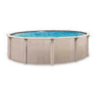
Related product manuals