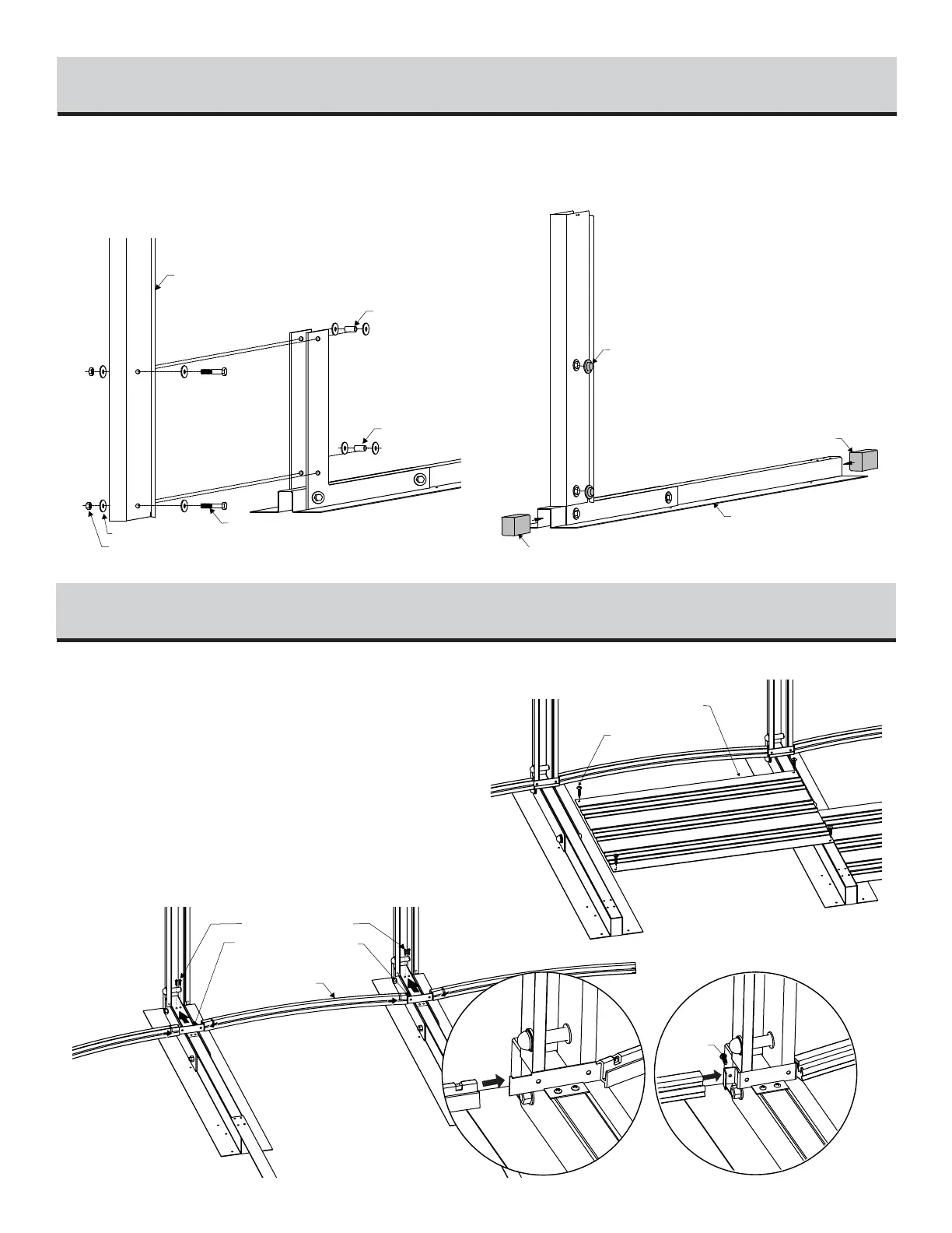
2) Refer to Illustration 4.2. Assemble the buttress post using
bolts 1/2" X 3" X #13 (12,7 mm X 76,2 mm) (U), nuts (UU) and
washers (V). Remember to insert a spacer (T) and two washers
(V) inside the butress post aligned to each bolt.
3) Refer to Illustration 4.3. Cover the bolt heads with bolt cap
covers (W) and insert the styrofoam block (X) at both ends of foot
beam.
STRAIGHT SECTION BUTTRESS ASSEMBLY (continued)
4
Illustration 4.3
Illustration 4.2
1) Position the buttress posts assembled in Step 4 on the patio
blocks in the trenches previously dug.
2) Refer to Illustration 5.1 : Once the buttress posts are placed in
the trenches, assemble the straight section bottom tracks between the but-
tress posts by fixing them on the bottom track jonction and fix them to the
foot beams using standard screws #14.
3) Refer to Illustration 5.2 : Fix the pressure plates between the
foot beams with four (4) standard screw ‘’Z’’.
BOTTOM TRACKS (straight section) AND PRESSURE PLATES
5
Illustration 5.1