Trident 88 Owners Manual26
Trident 88 Patchbay
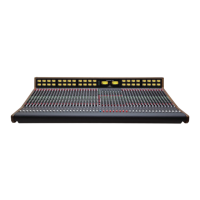
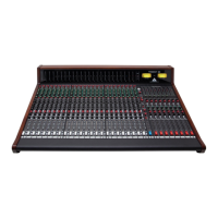
The balanced & Unbalanced connections are wired
per the following diagrams below:
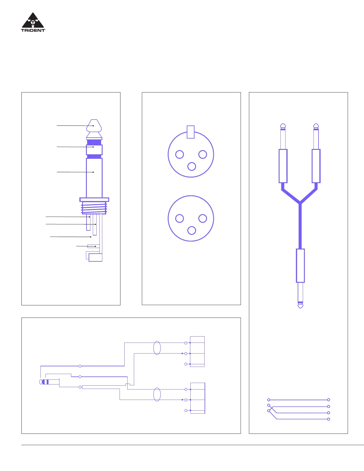
Tip Left
Ring
Right
Ground
Sleeve
Male XLRs
(+)
(-)
(S)
(+)
(-)
(S)
Left
Right
XLR Pin 2
XLR Pin 3
XLR Pin 1
XLR Pin 2
XLR Pin 3
XLR Pin 1
Unbalanced Stereo Mini TRS to Pin 2 Hot XLR Male adapter
for Walkman, DAT, CD or MD
Pin 1 connected on balanced side but not connected on insert side
Balanced use
of stereo 1/4” jack plugs
Balanced use
with XLR connectors
1 2
3
Input
For connection of balanced
and unbalanced sockets, ring and
sleeve have to be bridged at
the stereo jack.
Tip =
hot (+ve)
Ring =
cold (-ve)
Sleeve =
Ground / Shield
Tip
Ring
Sleeve
Strain relief clamp
For unbalanced, use pin 1
and pin 3 have to be bridged
1 = Ground / Shield
2 = Hot (+ve)
3 = Cold (-ve)
1 2
3
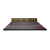
The example above shows
an example of the cable required
for connection to the Stereo EFX
Returns Alternate Speakers and
2 Track Returns. This is where you
sending Left and Right signal from
a single TRS point, much like one
would do for Headphones,
Channel Inserts, Group Inserts
and Master Insert.
Ring
Sleeve
Tip
Sleeve
Ring
Sleeve
Tip
Ring
Sleeve
Tip
Sleeve
Ring
Sleeve
Tip
Y-cable splitter with one
common 1/4” jack
 Loading...