Trident 88 Owners Manual 27
Trident 88 Patchbay
The Trident 88 is supplied with a high quality switch mode D.C. power supply. The power supply should
be connected to a suitable A.C. power source via the included earthed cable and connected to the 3 pin
I.E.C. socket at the rear of the power supply. The power supply will accept both 230 and 110 volts A.C.
It is recommended that the supply is placed in a well ventilated area on installation. Note the Trident 88
power supply is fit ed with a silent running fan. Low voltage D.C. is supplied to the console via a circular
locking connector. With the power supply switched o, this should be pushed firmly into the mating
socket on the rear of the console Master connector (behind the Master section). A locking ring ensures
that the cable cannot be accidently pulled from the console.
Once the power supply has been connected to the console, the power supply can be switched on. The
power supply is fit ed with four LED indicators which indicate that the +18, -18 and 48 volts are function-
ing. It should be noted that the Trident 88 power supply is fit ed with a fourth, 24 volt power mode, as
indicated on the front panel. Currently this is an unused feature and will be illuminated even though not
in use. If for any reason, the +18, -18 or 48 volt LED indicators fail to illuminate, check the corresponding
LED indicators on the console meter bridge, if they match, do not operate the console. Turn off the pow-
er supply immediately and contact Trident Audio Developments for qualified support
Trident 88 Power Supply
Composite
C M Y CM MY CY CMY K
Composite
C M Y CM MY CY CMY K
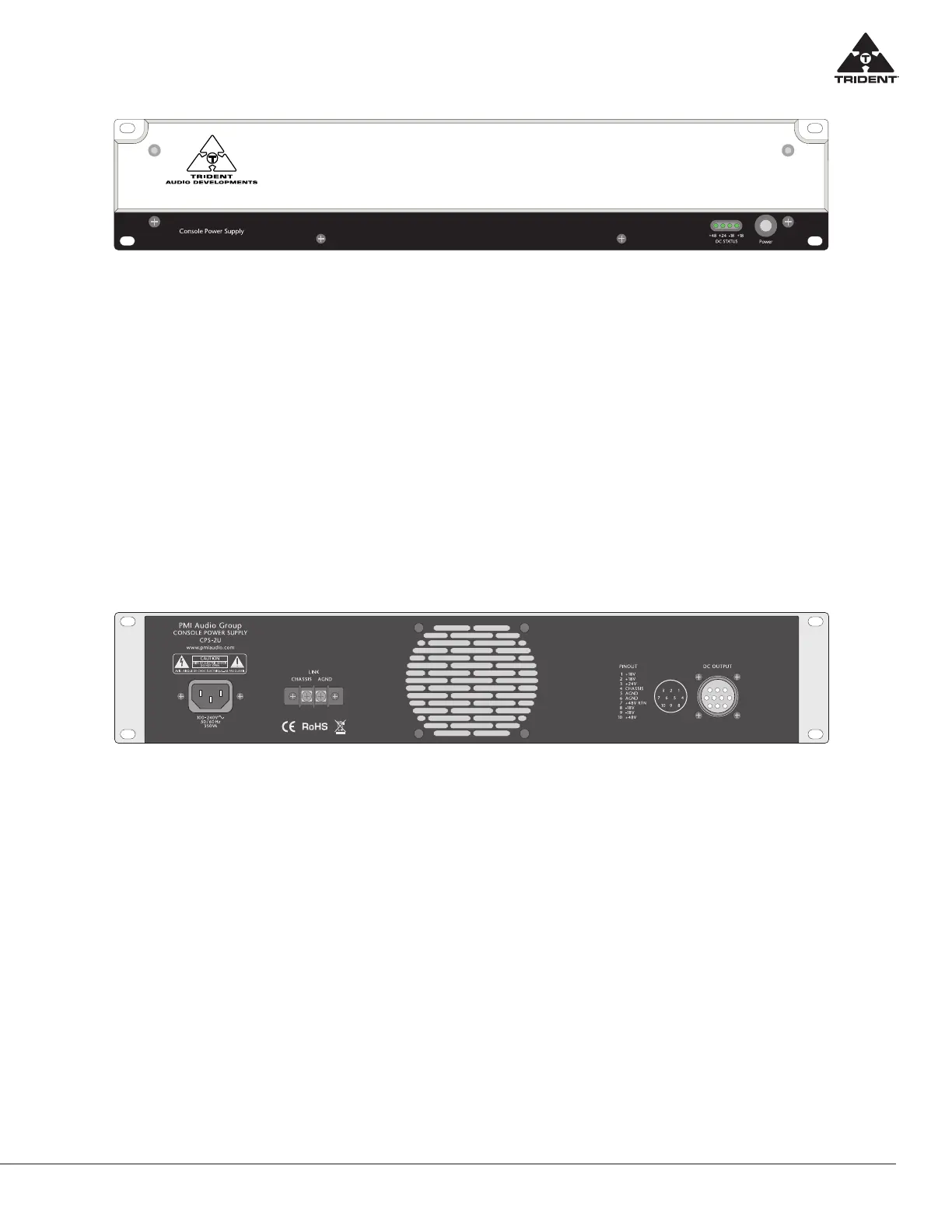
The rear of the power supply provides for a Star Ground Link connection point and it is highly recom-
mended that the console is set up using the Star Grounding method, as set out further on in the manual.
This Link connection provides a direct connection to the consoles internal ‘ground central’ point within
the console. Chassis and audio ground connections are provided on the Link connection, enabling the
chassis to be lifted from the audio ground. This is not recommended, however, if the proper grounding
rules are not adhered to it may be necessary to minimize ground loops lifting this connection.
The D.C. connections are as follows:
Pin 1 +18 Volts Pin 6 AGND
Pin 2 +18 Volts Pin 7 +48 Volts Return
Pin 3 +24 Volts Pin 8 -18 Volts
Pin 4 Chassis Pin 9 -18 Volts
Pin 5 AGND Pin 10 +48 Volts
Voltages can also be found via the diagram on the rear of the power supply.
 Loading...