8
When connecting a microphone, set the 'Input Level' control for each channel to minimum, with the
phantom power +48V switch off (LED extinguished). The microphone input is designed to accept
the signal from low impedance, balanced microphones of either dynamic, ribbon or condenser
types. The line input is designed to accept balanced or unbalanced, line level audio signals. Mic or
Line input is selected via the front panel 'Line' switch (LED lights for 'Line').
The outputs from each channel are low impedance and designed to operate with long cable runs
without signal degradation.
A standard IEC mains inlet is provided for AC mains power. Operating voltage of either 120 or 240
volts is selectable by rotating the fuse holder incorporated into the mains inlet socket.
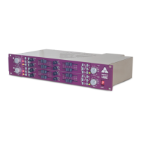
INPUT SECTION
The input section of the A-Range rack consists of a very high quality transformer-coupled discrete
microphone amplifier and transformer-coupled discrete line amplifier designed specifically for
professional audio applications.
The microphone and line transformers are custom designed to the exact original Trident A-Range
specifications.
A-Range
When using a line level signal, the 'Line' switch should be depressed (LED illuminates) and the 'Input
Level' control switched to '0'. +48V phantom power should never be selected in the 'Line' mode as
this can cause a loud noise when the phase reverse switch is operated. In this position with the
®
®
®
The microphone amplifier is designed to handle signal levels from -60dBu to as high as +10dBu
without needing a separate pad switch. The 15-position combined mic/line gain switch is calibrated
in accurate 5dB steps to provide precise matching of either microphone or line level signals. In
conjunction with the 'Output' level control, very fine adjustment of signal level is achievable. The
preamplifier exhibits very low noise while maintaining extremely fast transient response and a
frequency response that extends beyond 40kHz. Naturally, best results are achieved when using a
high quality condenser microphone. The microphone amplifier will also bring out the best in dynamic
and ribbon microphones.
When connecting a microphone to the input of the unit, set the 'Input Level' rotary switch to its
minimum ('0') position and the 'Output' level control to its '0' position. The 'Line' switch should not be
depressed. If required, engage the '+48V' phantom power switch while the 'Input Level' control is at
minimum. The associated LED will show that phantom power is present. Allow up to 30 seconds for
the microphone to reach normal operating level and advance the 'Input Level' control until a suitable
level is achieved at the output of the unit. The 'O/P peak' LED signal indicator at the output stage of
the circuit is designed to light when a signal level of +15dBu occurs at the output stage. This provides
plenty of overload margin as the is capable of very high output levels (up to +26dBu) into
a balanced load. However, by setting the level as described above, adequate headroom is
maintained and there should be no danger of overloading following equipment.
The phase (polarity) reverse switch is employed when phase interference occurs between multiple
microphones. Such interference results when microphones, at various placements, pick up the
same sound source at slightly different times. When the output of the microphones combine,
cancellation occurs at certain frequencies. This effect is known as comb filtering. Switching the
polarity on one microphone may serve to minimise this effect.
 Loading...