9
'Output' level control also set to '0', the unit is designed to give unity or 0dB gain. The line input gain
can be adjusted in accurate 5dB steps in the same way as the microphone amplifier. However, the
line input adjustment only operates between the +10 and -10 positions of the switch. In all other
positions, the line input reverts to zero or 'unity' gain.
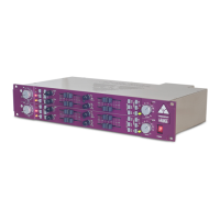
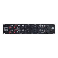
EQUALISER
The legendary A-Range equaliser is a unique and amazingly musical sounding equaliser - owing
much to its all-discrete transistor circuitry and the use of inductors in the lower and upper mid range.
The mid EQ sections are 'peaking', while the high and low range sections are 'shelving'.
Each of the four bands is rotary-switch-selectable to any one of four frequencies, while individual
push buttons engage the three high pass and three low pass filters.
A-Range
A-Range
A-Range
A-Range
Operating the Equaliser
®
®
®
®
®
A novel feature of the original console and incorporated in this unit, is the use of long-
throw faders for level adjustment, rather than rotary potentiometers. These faders feature a useful
centre dedent at mid travel to denote zero boost or cut of the selected frequency. The use of faders
makes it very easy to see not only when equalisation is being applied, but also the amount. A notable
difference in the operation of the sliders on the rack unit, versus the original console, is
one of physical orientation: the old console sliders move vertically, while the rack unit sliders move
horizontally. Accordingly, on the consoles, the slider moved up to 'boost' and down to 'cut', whereas
the rack version moves right to boost and left to cut. For most users, the layout adopted here will
seem logical. However for some engineers, accustomed to working with old modules
mounted sideways, this will seem backwards. This particular aspect of the design was the subject of
much consideration but in the end, it was decided that the rack unit should have a more conventional
'right to boost, left to cut'.
For those not familiar with the difference between a shelving and peaking equaliser, the differences
are as follows. A shelving equaliser boosts (or attenuates) all frequencies equally, above or below a
certain point. The frequency specified for a shelving equaliser circuit is usually at the point where it
effectively reaches its 'shelf' state. A 'high shelf' EQ boosts/cuts high frequencies and a 'low shelf'
type boosts/cuts low frequencies. This type of circuit is very popular in hi-fi systems but is also
actually highly musical, when applied in a recording environment. In contrast, a peaking equaliser is
one that, as its name implies, has a centre frequency that is boosted or attenuated more than others.
The frequency range over which it reaches its peak and then falls down is known as the bandwidth
(or 'Q'). Because this type of design reaches a peak and then falls away, it is possible with this type of
circuit to 'home in' on a particular area of frequencies and make adjustments without affecting those
around them. This can be particularly useful when working with instruments such as bass guitars
and snare drums. By incorporating both shelving and peaking equalisers into the design of the
, it is possible to get the best of both types of design.
Set the 'Input Level' in accordance with the procedures detailed in the 'Input Section' section of this
manual. Begin with all boost/cut faders set to their mid way ('0') positions. Adjust the low and high
mid frequency controls to their minimum positions (fully clockwise). The high and low pass filter
switches should be in their out positions. Set the frequency select switches controlling the high and
low shelving sections, to 150Hz and 12kHz respectively. Lastly, set the 'EQ' switch to the 'IN' position
(the associated LED will illuminate).
 Loading...