LIVELINK LAN DR
LIVELINK LAN DR
© trilux.com | 211217 |
10258341
7 | 36
10258341
| 211217 | © trilux.com6 | 36
EN
For your safety
Read all instructions and mounting steps carefully.
Keep the instructions for maintenance or disassembly
work.
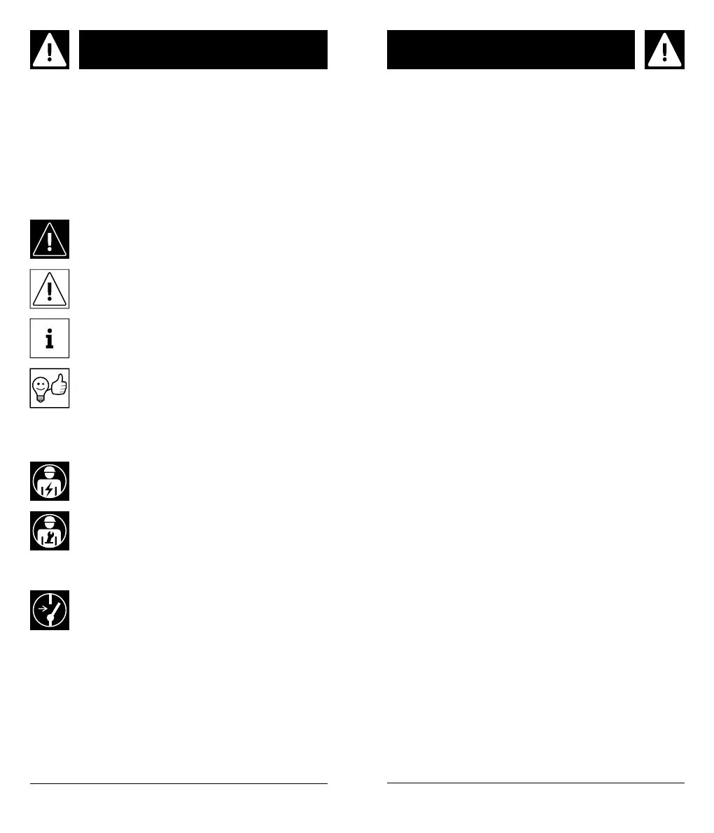
Explanation of the warning levels
Observe and follow the warnings.
Non-observance of the warnings may lead to injuries or
mat
erial damage!
WARNING! Indicates dangers which can
result in serious and/or fatal injuries.
CAUTION! Indicates dangers which can result
in injuries or health hazards.
NOTICE. Indicates dangers which
can result in material damage or malfunc-
tions.
TIP.
Indicates information containing advice
or a useful note.
Explanation of important symbols and
pictograms
Safety notes
Indicates professional personnel who are
trained and authorised to carry out the elec-
trical connection.
Indicates professional personnel who are
trained and authorised to carry out the
mounting.
WARNING! Risk of electric shock!
Never work with voltage applied.
EN
Important information on electronic control gear
units (ECG)
A neutral conductor interruption in the three-phase
circuit leads to overvoltage damage in the lighting sys-
tem. Only open the neutral conductor isolating terminal
in de-energised state, and close the neutral conductor
isolating terminal before switching on again. Do not
exceed the maximum permissible ambient temperature
t
a
of the luminaire.
Exceeding this limit reduces the service life
and in
extreme cases there is a risk of premature
failure of the
luminaire. Design connection cables for the control
inputs of DALI control gear (1-10 V, DALI etc.) to be 230
V mains voltage-proof (basic insulation).
Important notes on control units
• Do not exceed the maximum permissible ambient
temperature ta of the control unit. Exceeding this
limit reduces the service life, and in extreme cases
there is a risk of premature failure of the control
unit.
• Lay out the connection cables for the control inputs
of DALI control gear 230 V mains voltage-proof
(basic insulation).
• A maximum of 64 DALI loads per DALI bus are
permitted.
• A maximum of 10 gateways can be connected in
series.
Important notes for checking the installation
Check the installation before commissioning. To
check the installation the gateway features a function
for the broadcast identification of all connected de-
vices.
• Short key press (Test key): all devices flash
• Press the key again (Test key): all devices stop
flashing
• Key press for 10 s (Reset key): Gatway is reset to
factory settings
 Loading...