XCN-1050 DISPLAY SYSTEM
Description Use to ...
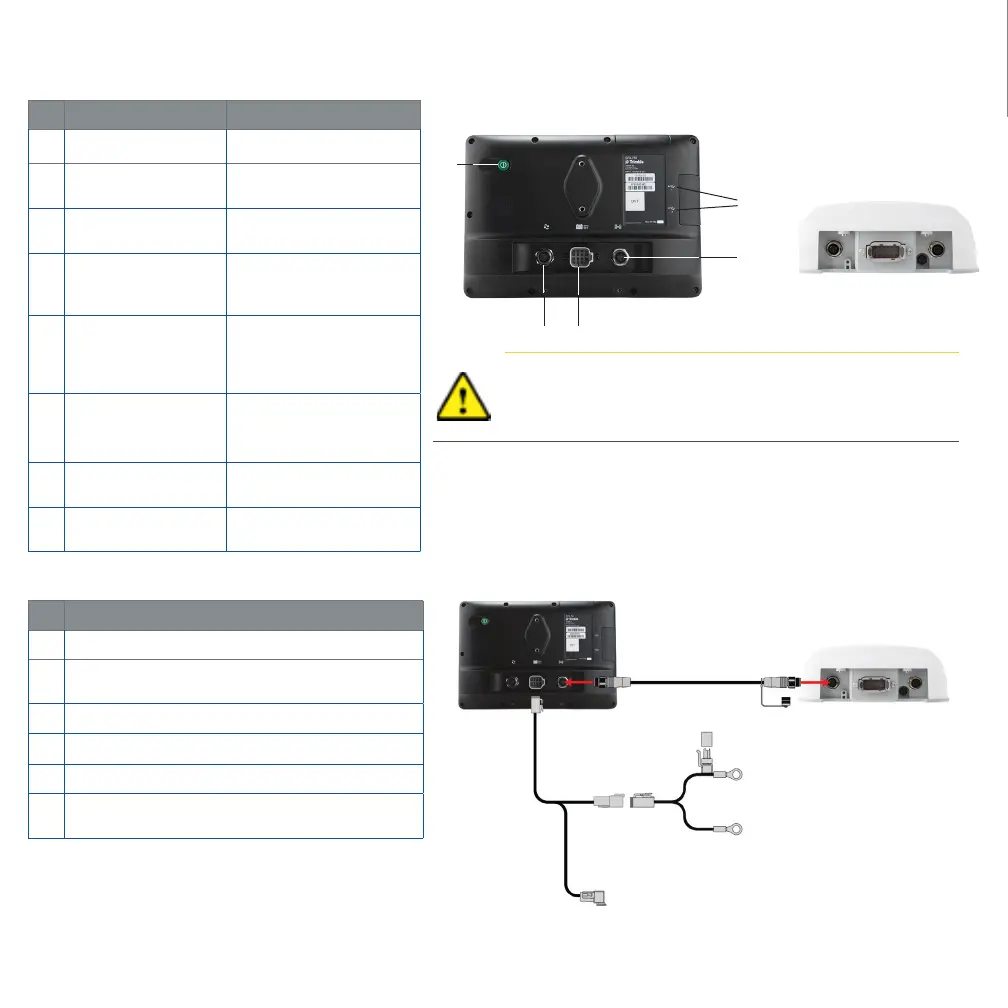
c
Power button Turn the display on or o.
d
Expansion Port
(5-pin B code)
Connect to various inputs
and outputs.
e
Main Power
connector
Powers display system
(including the NAV-900).
f
Power/Ethernet Port
(4-pin D code)
Connects to NAV-900
Guidance controller
(power/GNSS).
g
USB sockets
Connect a USB memory
stick to the display to
transfer data to and from
the unit.
h
Power/Ethernet Port
(4-pin D code).
Connects to XCN-1050
(power/GNSS)
i
Main Port- 12 pin
DTM.
Connects to various Auto
Guidance systems.
j
RTK Radio Port
(5-pin A code).
Connects to various RTK
radios.
Description
c
XCN-1050 Display
d
XCN-1050 Display to NAV-900 Guidance Controller
cable
e
NAV-900 Guidance Controller
f
XCN-1050 System Power and CAN (1) Display cable
g
XCN-1050 System Power (Battery Cable)
h
P2 CAN Port. Uses adapters to connect to CAN
implement devices (ISO and Field-IQ Basic)
Caution! Some connectors may appear similar, but are coded
dierently to ensure correct component mating. Check that
you have the correct cable before connecting, and do not use
excessive force or damage may result.
9
❶
❷
❺
❹
❸
❺
❹
❼
❶
❷
❸
❽
❻
❻