TrinityHighway.com 21 Revision A November 2021
CCT Posts Assembly
Terminal Posts
The CCT consists of three (3) CRPs and six (6) S3 x 5.7# [S75 x 21] terminal line posts
(positioned in a sleeve or a driven post).
Cable Release Post (CRP) – Post 1 to Post 3
Complete the following steps for the placement of the CRP.
1.
Place the top CRP (PN-33935A) on the assembled bottom CRP.
2.
Place PN-4211G bolt in the two holes of the sloping plates of the top and bottom CRP.
3.
Place a PN-3240G and PN-3245G on each of the bolts.
4.
Tighten the nuts to a snug position with a minimum of two (2) bolt threads protruding
beyond the nut.
Terminal Line Posts in Sleeve (Concrete Footing) – Posts 4 to 9
Complete the following steps for the placement of the terminal line posts in the sleeve:
1.
Place the post sleeve cover (PN-5839B) on the bottom end of the terminal line
post (PN-33910G).
2.
Place posts in sleeves 4 to 9. The cover will be located at the top of the sleeve.
Terminal Line Posts in Driven Sleeve-Posts 4 to 9
1.
Complete the following steps for the placement of the terminal line posts in the driven
sleeve: Place the post sleeve cover (PN-5839B) on the bottom end of the terminal line
post (PN-33910G).
2.
Place posts in sleeves 4 to 9. The cover will be located at the top of the sleeve
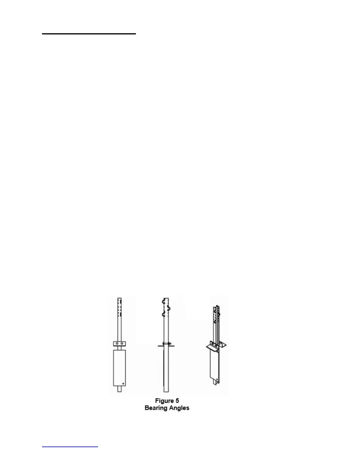
3.
Place a bearing angle (PN-9021G) on each side of the post 4 at the ground line (See
Figure 5).
4.
Place two (2) hex bolts (PN-4779G) and flat washers (PN-3701G) through the two (2)
bearing angles. Place a hex nut (PN-3711G) and flat washer (PN-3701G) on the bolt.
Tighten the nuts to a sung position with a minimum of two (2) bolt threads protruding
beyond the nut.