PRINCIPLES of OPERATION
The Model PF-810 is composed of four major units,
a directional coupler, a voltage converter, an indicator
and a switching unit; all units except the antenna selector
and the directional coupler, function as a DC circuit.
Directional coupler
The directional coupler is used to pick up a very small
power from the coaxial cable connected between trans-
mitter and load by separating forward wave and refrec-
tion wave components.
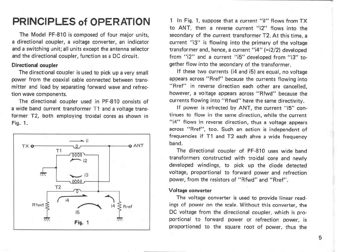
The directional coupler used in PF-810 consists of
a wide band current transformer T1 and a voltage trans-
former T2, both employing troidal cores as shown in
Fig. 1.
iI
TX
ANT
Rfwd
~
1 In Fig. 1, suppose that a current "il" flows from TX
to ANT, then a reverse current "i2" flows into the
secondary of the current transformer T2. At this time, a
current "i3" is flowing into the primary of the voltage
transformer and, hence, a current "i4" (=i2/2) developed
from "i2" and a current "i5" developed from "i3" to-
gether flow into the secondary of the transformer.
If these two currents (i4 and i5) are equal, no voltage
appears across "Rref" because the currents flowing into
"Rref" in reverse direction each other are cancelled,
however, a voltage appears across "Rfwd" because the
currents flowing into "Rfwd" have the same directivity.
If power is refrected by ANT, the current "i5" con-
tinues to flow in the same direction, while the current
"i4" flows in reverse direction, thus a voltage appears
across "Rref", too. Such an action is independent of
frequencies if T1 and T2 each ahve a wide frequency
band.
The directional coupler of PF-810 uses wide band
transformers constructed with troidal core and newly
developed windings, to pick up the diode detected
voltage, proportional to forward power and refrection
power, from the resistors of "Rfwd" and "Rref".
Voltage converter
The voltage converter is used to provide linear read-
ings of power on the scale. Without this converter, the
DC voltage from the directional coupler, which is pro-
portional to forward power or refrection power, is
proportioned to the square root of power, thus the
5
T1
i2
"-- i3
"")
-.
i4 '$ Rref
i5
Fig. 1