CAUTIONS
1. Connect cables firmly to the TX and ANT con.
nectors confirmingthe direction of connection.
2. PF-810 has 50-ohm of impedanceand should be con-
nected with 50.ohm cables. If it isto be connected to
a device of different impedance (75-ohm, etc.), be
sure to use a matching transformer or an antenna
coupler.
3. Keep your hand off the internal circuit.
4. If SWR of load being used is unknown, the high
frequency voltage of PF-810 may be increased ex-
cessively depending on the length of cable or the
condition of load. In this case, adjust the power as
small as possible for accurate impedance matching.
Whenthe impedance matching is completed, then set
the transceiverfor fu11power.
5. Do not touch the antenna selector pushbutton while
the transmitter is in operation. Besure to turn off the
power wheneverthe antenna selector isused.
OPERATION
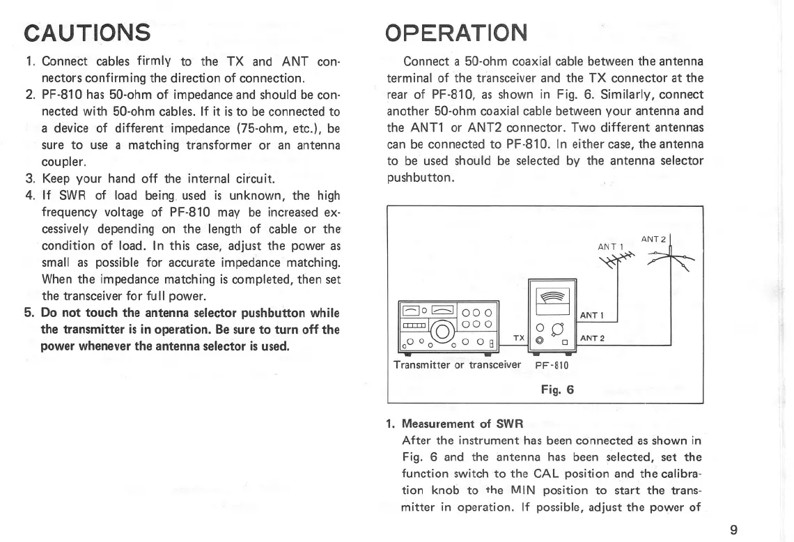
Connect a 50-ohm coaxial cable between the antenna
terminal of the transceiver and the TX connector at the
rear of PF-810, as shown in Fig. 6. Similarly, connect
another 50.ohm coaxial cable between your antenna and
the ANT1 or ANT2 connector. Two different antennas
can be connected to PF-810. In either case, the antenna
to be used should be selected by the antenna selector
pushbutton.
Transmitter or transceiver
ANT2
ANT 1
~IIANTI
0 0 IIANT2
TXII@ 0
PF-810
Fig. 6
1. Measurement of SWR
After the instrument has been connected as shown in
Fig. 6 and the antenna has been selected, set the
function switch to the CAL position and the calibra-
tion knob to the MIN positi on to start the trans-
mitter in operation. If possible, adjust the power of
9