Operating Instructions
AC/DC Voltage Measurements
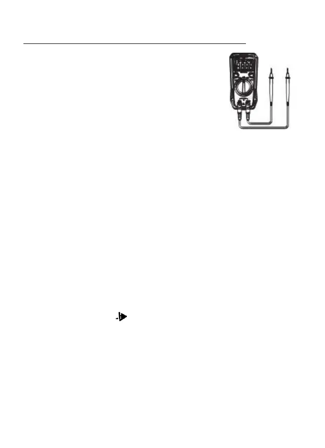
1. Insert the black test lead banana plug into the negative COM
jack and the red test lead banana plug into the positive V
jack.
2. Turn the rotary switch to the V position.
3. Press the SELECT button to select either AC or DC.
4. Touch the test probes to the circuit under test and read the
voltage on the display.
**NOTE: The
meter
has
the function
of
ACV/DCV
automatic
identification (voltage
≥
0.5V).
If you
want
to measure
voltage
less
than
0.5V,
press the
SELECT
button
to
toggle
the
AC and
DC
voltage to lock the measurement
mode;
After pressing
the
SELECT
button, the meter no longer has the function
of
ACV
/DCV
automatic
identification,
unless you turn
the
range switch or restart the meter!**
Resistance Measurements
1. Insert the black test lead banana plug into the negative COM jack and the red test lead
banana plug into the positive Ω jack.
2. Set the function switch to the Ω position.
3. Touch the test probe tips across the circuit or part under test. It is best to disconnect one
side of the part under test so the rest of the circuit will not interfere with the resistance
reading.
4. Read the resistance in the display.
Continuity Measurements
1. Insert the black test lead banana plug into the negative COM jack and the red test lead
banana plug into the positive V/Ω/mA jack. Observe polarity.
2. Turn the rotary switch to the •))) position.
3. Touch the test probes to the circuit or device under test. If the resistance is less
than approximately 30Ω the buzzer will sound.
**NOTE: Before making Continuity Measurements make sure circuit power is OFF
and fully discharge any Capacitors to avoid damage to the meter.
 Loading...