3
Single Extender Installation
Note: Prior to connecting the RJ45 cable to input/output ports, install the included
water-resistant dust caps onto the cable. Caps can be screwed onto the end of the port
connection.
1. Using a Cat5e/6 cable (up to 100 m / 328 ft. long), connect your
powered source device (such as a PoE switch) into the “IN” port on the
unit.
2. Using another Cat5e/6 cable (up to 100 m / 328 ft. long), connect
your remote PoE powered device (PD) (such as VoIP or IP surveillance
camera) into the “OUT” port on the unit.
Note: Your PoE source must meet or exceed IEEE 802.3at / 802.3af standards.
Please see Maximum Supported Power table for more information.
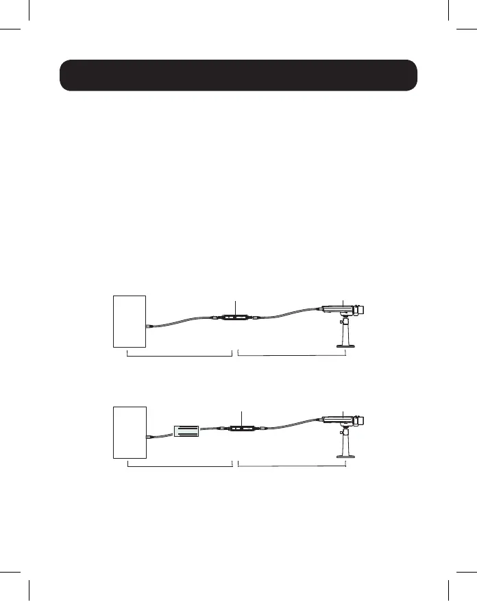
Single Extender Installation Diagram
Single Extender Installation with Midspan Diagram
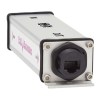
CameraPoE Extender
PoE
Switch
Max 100 m (328 ft.) Max 100 m (328 ft.)
CameraPoE Extender
Switch
(Non-PoE)
Midspan
Max 100 m (328 ft.) Max 100 m (328 ft.)
Note: Where external power is required, the power source (e.g.. midspan or PoE
injector) must be installed between the Ethernet switch (non-PoE source) and the first
NPOE-EXT-1G30WP extender.
18-12-180-9338F9.indb 3 4/17/2019 10:22:30 AM
 Loading...