5
Installation
3-3
Connect SRCOOLNET to Computer: Usetheincludedmini-DINtoDB9
configurationcable(partnumber73-1025)toconnecttheSRCOOLNETtothe
computer. The circular connector
D
at one end of the cable attaches to the
8-pinmini-DINserialport(labeledCONFIG)
E
ontheSRCOOLNET(Alignthe
connectorcarefullytoavoiddamagingthepins).TheDB9connector
F
at the
other end of the cable connects to the computer’s serial port
G
.
Note: Self-adhesive Velcro strips are included for mounting the SRCOOLNET to the
side of the A/C unit. As an alternative, the included rubber feet can be used if the
SRCOOLNET will be freestanding.
3-4
Connect SRCOOLNET to Network: Connect a standard Ethernet patch cable to
theRJ45EthernetportontheSRCOOLNET.Note: This port does not support
PoE (Power over Ethernet) applications.
3-5
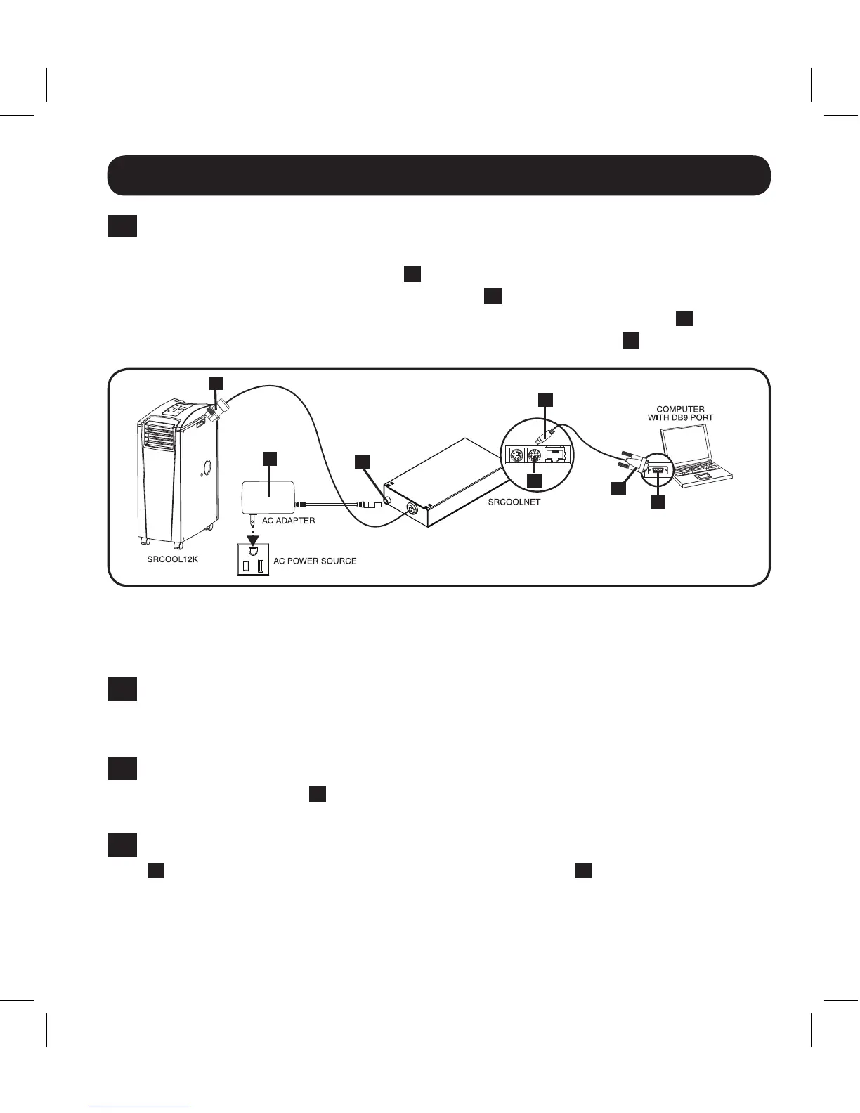
Connect the SRCOOLNET to the SRCOOL12K or SRXCOOL12K: Usingthe
dedicated connector
A
, connect the SRCOOLNET to the communication port on
thesideofthespotcooler(RefertoFigure1).
3-6
Connect SRCOOLNET to Power: (RefertoFigure1).ConnecttheACAdapter
B
totheSRCOOLNETviatheportlabeled“DCPower”
C
and plug the other
endintoanACpowersource.
Note: The SRCOOLNET must be plugged into a power source protected by a UPS
or Inverter/Charger in order to maintain communications during a power outage.
Figure 1
A
B
D
G
C
E
F
13-08-187 93-32CA.indb 5 9/27/2013 9:25:20 AM