TW10i
8
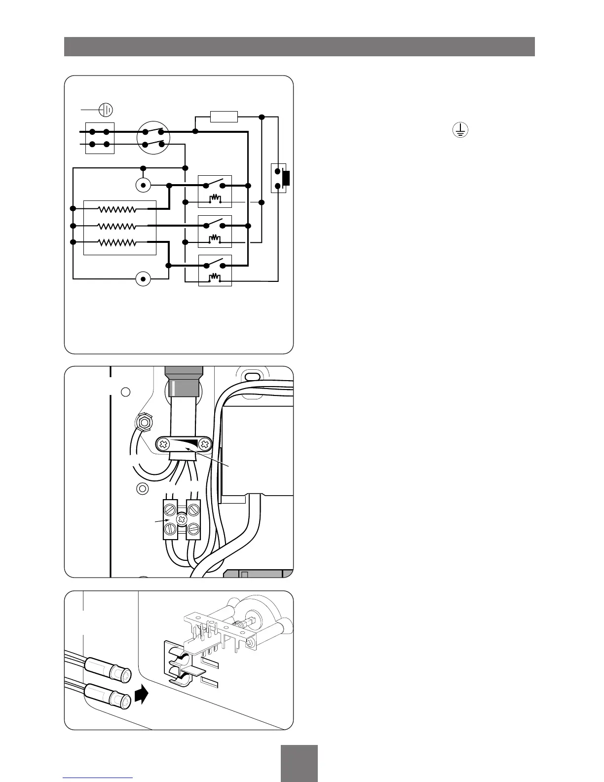
Route the cable into the heater unit and connect
to terminal block (fig.14) as follows:-
Earth cable to terminal marked
Neutral cable to terminal marked
N
Live cable to terminal marked L
Important:
Fully tighten the terminal block screws
and ensure that no cable insulation is trapped
under the screws. NOTE: The supply cable earth
conductor must be sleeved.
The outer sheath of the supply cable must be
stripped back to just after the clamp.
The cable clamp (fig.14) is suitable for up to four
mm
2
cable or can be reversed for use with up to
ten mm
2
cable. The earth continuity conductor of
the electrical installation must be effectively
connected electrically to all exposed metal parts of
other appliances and services in the room in which
the heater is to be installed, to conform to current
IEE regulations.
DO NOT switch on the electricity supply until
the cover has been fitted.
REPLACING THE COVER
Offer the cover to the backplate and plug the two
loose neons into the bracket that is located inside
the cover (fig.15) ensuring that the neon with the
grey wires is placed in the upper position and the
neon with the yellow wires is placed in the lower
position.
While supporting the cover (it is not advisable to
let the cover dangle with the weight taken by the
neon wires) connect the two loose brown wires
attached to the backplate unit to the two brown
wires attached to the switch assembly located
inside the cover
(fig.16). These are male and
female spade connectors and simply push in.
Carefully replace the cover by first engaging the
lug on the right hand side into the location hole
on the backplate
(fig.17).
Swing the left side onto the backplate ensuring no
cables etc. are trapped. Secure with the retaining
screw. Replace the cover trimplate by pushing into
place.
 Loading...