GEARBOX
Fig.
14
Removing Mainshaft Centre Bearing with
Churchill
Press No.
S4221
and
adapter
from Set No.
S4615
(q)
Lift
out the reverse pinion (compound
gear) after tapping out its spindle
through the rear of the casing, the
retaining setscrew having been re-
moved in a previous operation (h).
(r)
The countershaft assembly
can
now-
be
Mied out of the casing
with
the needle
roller retaining tube still locating the
24 rollers at each end of the
counter-
shaft
in
their respective recesses. Lay
aside the two phosphor bronze thrust
washers for re-assembly.
(S)
The countershaft gears and distance
sleeve
can
now be removed from the
splined portion of the countershaft,
noting their position for re-assembly.
(t)
If it is desired to examine the needle
rollers they
can
be removed by with-
drawing the retaining tube. Note the
correct number of
48
for re-assembly
(24 at each end) and the needle roller
retaining rings can be tapped out with
a suitable drift.
9.
TO
ASSEMBLE
(a)
Thoroughly clean out the casing and
examine for cracks, ball race housings
for
wear
or other damage.
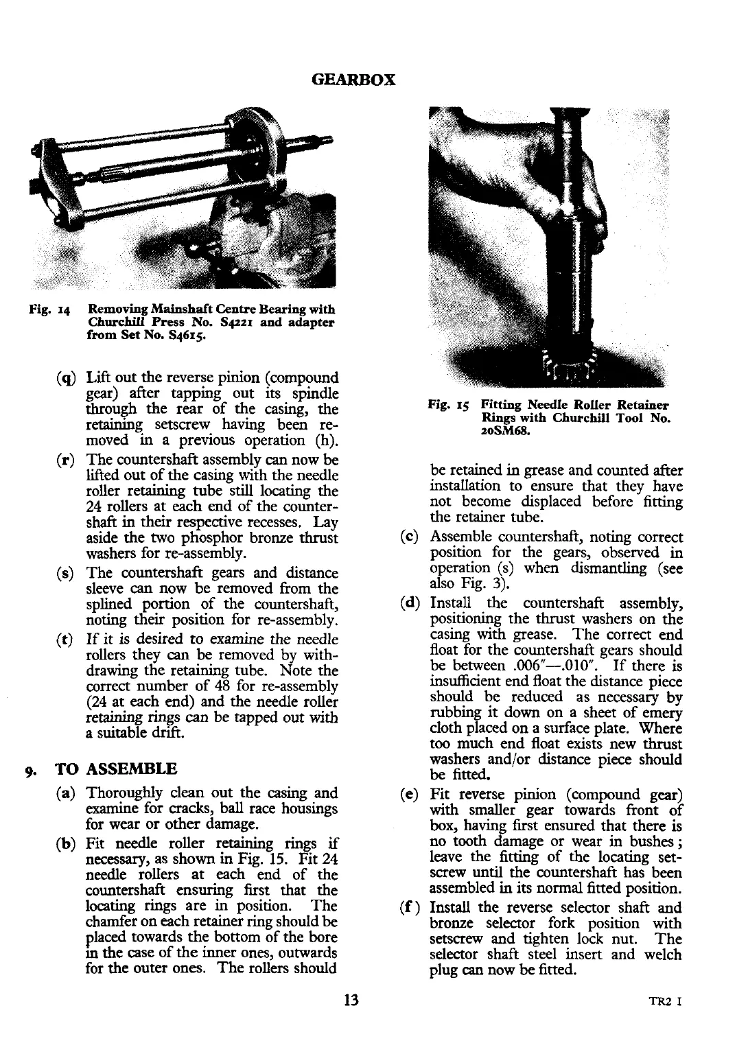
(b)
Fit needle roller retaining rings
if
necessary, as shown in Fig. 15. Fit 24
needle rollers at each end of the
countershaft ensuring first that the
locating rings are in position. The
chamfer on each retainer ring should be
placed towards the bottom of the bore
m
the case of the inner ones, outwards
for the outer ones. The rollers should
Fig.
15
Fitting
Needle Roller Retainer
Rings
with
Churchill
Tool No.
2oSM68.
be retained in grease and counted after
instauation to ensure that they have
not become displaced before fitting
the retainer tube.
(c)
Assemble countershaft, noting correct
position for the gears, observed in
operation
(S) when dismantling (see
also Fig.
3).
(d)
Install the countershaft assembly,
positioning the thrust washers on the
casing with grease. The correct end
float for the countershaft gears should
be between
.006"-.010".
If there is
insufficient end float the distance piece
should be reduced as necessary by
rubbing it down on a sheet of emery
cloth placed on a surface plate. Where
too much end float exists new
thrust
washers and/or distance piece should
be
fitted.
(e)
Fit reverse pinion (compound gear)
with
smaller gear towards front of
box, having first ensured that there is
no tooth damage or wear in bushes
;
leave the fitting of the locating set-
screw
until
the countershaft has been
assembled in its normal fitted position.
(f)
Install the reverse selector shaft and
bronze selector fork position with
setscrew and tighten lock nut. The
selector shaft steel insert and welch
plug
can
now
be
fitted.
 Loading...


