REAR
AXLE
between the
"
head
"
bearing outer ring
and the casing. Preloading of bearings is
adjusted by means of shims between the
spacer and tail bearing.
The differential casing contains two sun and
two planet wheels and also carries the crown
wheel, which is bolted in position by ten
bolts passing through the casing and into
tapped holes in the back of the wheel itself.
NOTE
2
:
Fig.
1.
The crown wheel is
attached to the differential casing by
bolts locked by tab washers. The crown
wheel showed a tendency to work
loose after exacting rally acceleration
and reversing gear tests and to ob-
viate this possibility the
h"
UNF
attachment bolts were replaced by
8"
UNF in axles numbered TS.4731
onwards.
The two planet wheels are mounted on a
cross spindle, this spindle being provided
with a hole at one end and located by a pin
passing through the hole and the differen-
tial casing.
NOTE
1
:
Fig.
1.
The locating pin used
has a
"
stepped
"
shape but this is to
be changed in the near future to the
"parallel" type pin as shown in the
main illustration. Incorporated in
axle No. TS.6260 onwards.
The axle shafts are splined at both ends.
The inner end fitting into the sun wheels
and the outer extremity accommodating the
wheel bearing and hub. The hub is
secured to the splined end of the axle shaft
by means of a splined taper collar, a shaped
washer and a castellated nut.
The wheel bearing is accommodated
in
the
axle sleeve and
a
housing which is bolted to
the flanged end of each axle tube. The inner
portion of the wheel bearing is gripped
between the hub and a flange on the axle
shaft.
The differential casing is mounted on two
taper roller bearings, the position of these
being adjusted by means of shims inter-
posed between them and the casing itself.
The disposition of these shims decides the
crown wheel and pinion depth of engage-
ment and the thickness of these the
amLunt
of pre-loading.
2.
TO
REMOVE
HUBS
(a)
Remove the nave plate.
(b)
Withdraw the split pin from end of
axle shaft. Partly release the torque on
the castellated hub securing nut.
(c)
Jack up the car, remove the castellated
nut, the road wheel and by the with-
drawal of the two countersunk set-
screws remove the brake drum.
(d)
Remove the washer and the splined
taper collar from the axle shaft.
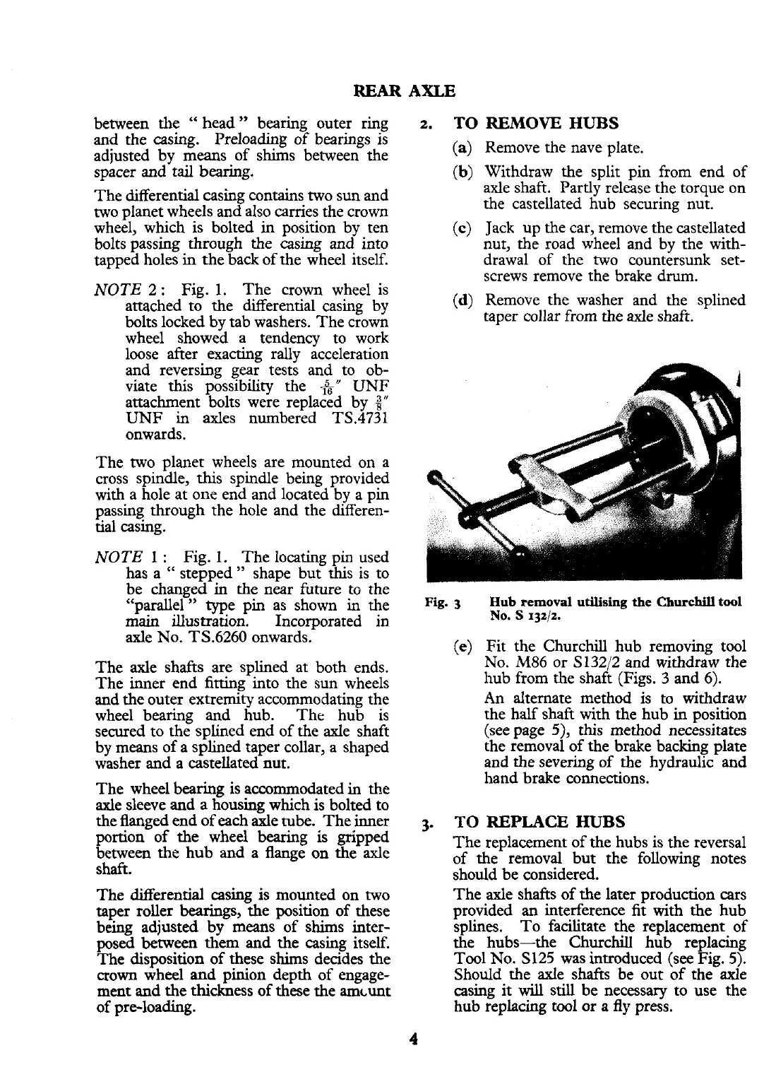
Fig.
3
Hub
removal
utilising
the
Churchill
tool
NO.
S
132/2.
(e)
Fit the Churchill hub removing tool
No. M86 or S13212 and withdraw the
hub from the shaft (Figs. 3 and 6).
An
alternate method is to withdraw
the half shaft with the hub in position
(see page
5),
this method necessitates
the removal of the brake backing plate
and the severing of the hydraulic and
hand brake connections.
3.
TO
REPLACE
HUBS
The replacement of the hubs is the reversal
of the removal but the following notes
should be considered.
The axle shafts of the later production cars
provided an interference fit with the hub
splines. To facilitate the replacement of
the hubs-the Churchill hub replacing
Tool No. S125 was introduced (see Fig. 5).
Should the axle shafts be out of the axle
casing it
will
still be necessary to use the
hub replacing tool or a
fly
press.
 Loading...


