BODY
It
will
be necessary to drop this su port rod
clear of the studs and this
will
be
p
acilitated
by slackening off the upper nuts on each
arm of the
"U"
(Fig. 10). Locate the de-
mister nozzles (1) on the two pairs of studs
ensuring that they are above and clear of
the screen wiper drive cable. Reposition
"U"
shaped rod and refit nuts and washers
on the four studs and retighten with a
suitable spanner.
9.
At this point it is advisable to install the
electrical control switch (Fig. ll), a hole
for which is already provided in the dash-
board. For the sake of appearance the hole
in the dashboard is covered by trim material
until it is required. This covering of trim
can easily be cut away with a small sharp
blade, after location of the hole with the tip
of a finger, its position is approximately
4
from the steering end of the dashboard at a
point
29"
from the lower edge of the dash
panel.
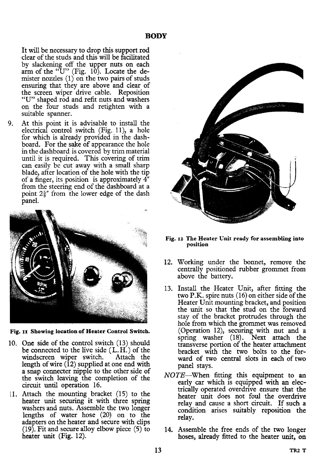
Fig.
11
Showing location of Heater Control Switch.
One side of the control switch (13) should
be connected to the live side
(L.
H.) of the
windscreen wiper switch. Attach the
length of wire (12) supplied at one end with
a snap connecter nipple to the other side of
the switch leaving the completion of the
circuit
until
operation 16.
Attach the mounting bracket (15) to the
heater
unit
securing
it
with three spring
washers and nuts. Assemble the two longer
lengths of water hose (20) on to the
adapters on the heater and secure with clips
(19). Fit and secure alloy elbow piece (5) to
heater unit (Fig. 12).
Fig.
12
The Heater Unit ready for assembling into
position
12. Working under the bonnet, remove the
centrally positioned rubber grommet from
above the battery.
13. Install the Heater Unit, after fitting the
two
P.K.
spire nuts (16) on either side of the
Heater Unit mounting bracket, and position
the
unit
so that the stud on the forward
stay of the bracket protrudes through the
hole from which the grommet was removed
(Operation
12), securing with nut and a
spring washer (18). Next attach the
transverse portion of the heater attachment
bracket with the two bolts to the for-
ward of two central slots
in
each of two
panel stays.
NOTE-When fitting this equipment to an
early car which is equipped with
an
elec-
trically
operated overdrive ensure that the
heater unit does not foul the overdrive
relay and cause a short circuit.
If
such a
condition arises suitably reposition the
relay.
14. Assemble the free ends of the two longer
hoses, already fitted to the heater
unit,
on
 Loading...


