BODY
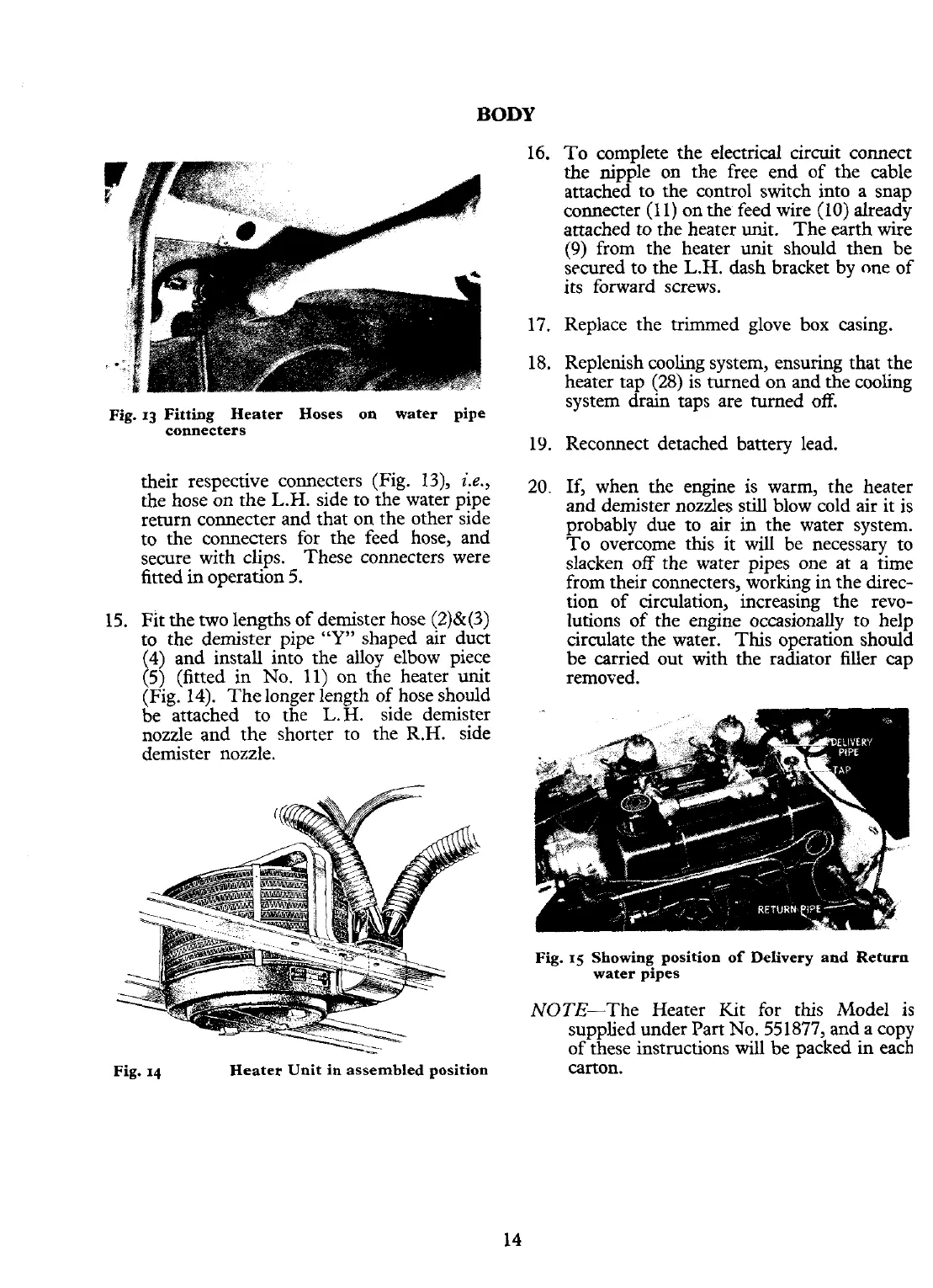
Fig.
13
Fitting Heater Hoses on water pipe
connecters
their respective connecters (Fig. 13),
i.e.,
the hose on the
L.H.
side to the water pipe
return connecter and that on the other side
to the connecters for the feed hose, and
secure with clips. These connecters were
fitted in operation
5.
15. Fit the two lengths of demister hose (2)&(3)
to the demister pipe
"Y"
shaped air duct
I
4) and install into the alloy elbow piece
5)
(fitted in No. 11) on the heater unit
(Fig. 14). Thelonger length of hose should
be attached to the L.H. side demister
nozzle and the shorter to the R.H. side
demister nozzle.
Fig.
14
Heater Unit in assembled position
16. To complete the electrical circuit connect
the nipple on the free end of the cable
attached to the control switch into a snap
connecter (l l) on the feed wire (10) already
attached to the heater unit. The earth wire
(9)
from the heater unit should then be
sccured to the
L.H.
dash bracket by one of
its forward screws.
17. Replace the trimmed glove box casing.
18. Replenish cooling system, ensuring that the
heater tap (28) is turned on and the cooling
system drain taps are turned off.
19. Reconnect detached battery lead.
20.
If,
when the engine is warm, the heater
and demister nozzles still blow cold air it is
probably due to air
in
the water system.
To overcome this it will be necessary to
slacken off the water pipes one at a time
from their connecters, working in the direc-
tion of circulation, increasing the revo-
lutions of the engine occasionally to help
circulate the water. This operation should
be carried out with the radiator filler cap
removed.
Fig.
15
Showing position of Delivery and Return
water pipes
NOTE-The Heater Kit for this Model is
supplied under Part No. 551877, and a copy
of these instructions
will
be packed
in
each
carton.