Do you have a question about the Trocen TC-6832 and is the answer not in the manual?
States the copyright and modification rights of the manual and product.
Introduces the purpose of the manual and expresses gratitude to customers.
Provides contact information for technical and after-sales support.
Defines the target audience and purpose of the manual.
Introduces the TC-6832 motion controller and its key features.
Refers to external instructions for the TroCutCAD software.
Defines key terms and abbreviations used throughout the manual.
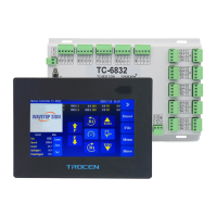
Illustrates the visual appearance and dimensions of the control panel.
Details the visual appearance and connection ports of the baseplate.
Describes the baseplate power port and its pin configuration.
Explains how the panel connects to the baseplate via serial ports.
Details the baseplate's input signal terminals for data acquisition.
Explains output voltage and required connection for peripherals.
Provides instructions for connecting motor drivers to the wiring board.
Briefly mentions the installation of TroCutCAD software.
Explains the Cartesian coordinate system for translation axes.
Explains coordinate values and behavior for rotary axes.
Guides on connecting the various hardware components of the system.
Instructions for connecting limit switches to the system axes.
Guidance on connecting input signals to the control system.
Details on connecting output ports to peripherals.
Recommendations for installing the system's power supply.
Instructions for establishing system communication via network or USB.
Steps for installing the required TroCutCAD software.
Verifies the correct installation of the power supply unit.
Ensures limit switches are correctly installed and configured.
Tests the functionality and connections of the output ports.
Configures axis reset directions and key functions for proper operation.
Commissioning the pulse equivalent for the X-axis movement.
Applies X-axis DPP commissioning to Y, UD, and U axes.
Sets the size parameters for the X, Y, Z, and UD1 axes.
Instructions for installing the vibrating blade and checking its direction.
Navigating to the interface for setting high and low points.
Procedure for setting the low point for the UD1 axis.
Sets the starting point for R-axis Distance Per Pulse commissioning.
Navigates to R-axis parameter settings for initial angle adjustment.
Enters the factory parameters to access offset setting options.
Positions the cutter head on paper for offset parameter calibration.
Moves the cutter head to align with reference marks for offset calibration.
Confirms the modification of offset parameters after adjustment.
Tests offset parameters and modifies X/Y values until overlap is achieved.
Sets the machine's zero position.
Configures the start and end points for operational sequences.
Defines the calculation for key movement acceleration.
Addresses issues related to stuck points due to acceleration or speed settings.
Defines safe moving speed as the minimum of safe and idle speeds.
Procedure for returning the machine to its anchor point after completion.
Process for testing the machine's running performance and speeds.
Defines the Space speed parameter affecting knife movement during cutting.
Defines the Cut Jerk parameter related to acceleration from take-off speed.
Defines the Cut Decel Jerk parameter for deceleration change.
Defines Space Jerk, affecting air travel speed.
Defines Space Decel Jerk, affecting deceleration and acceleration.
Defines Min Acc, affecting speed change at corners during cutting.
Guides on connecting the hardware components for initial setup.
Describes the function and description of each motion axis.
Instructions for connecting limit switches to the system axes.
Guidance on connecting input signals to the control system.
Details on connecting output ports to peripherals.
Recommendations for installing the system's power supply.
Instructions for establishing system communication via network or USB.
Steps for installing the required TroCutCAD software.
Verifies the correct installation of the power supply unit.
Ensures limit switches are correctly installed and configured.
Tests the functionality and connections of the output ports.
Configures axis reset directions and key functions for proper operation.
| Brand | Trocen |
|---|---|
| Model | TC-6832 |
| Category | Security Sensors |
| Language | English |