Do you have a question about the Trotec BE17 and is the answer not in the manual?
Defines signal words and symbols used in the manual for hazard indication and information.
Describes the required knowledge and skills for personnel working with electrical systems.
Explains the function and display of the voltage detector and its intended use categories.
Instructions for testing the device's reliable functioning before each voltage detection.
Notes on DC voltage display limitations and actual voltage interpretation based on display tolerance.
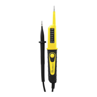
The BE17 is a bipolar voltage detector designed to indicate voltage ranges between 12 and 400 V DC or 12 and 400 V AC. It is suitable for use in facilities of overvoltage category 3 (CAT III = domestic installations). The device provides a visual indication of voltage amounts across 7 sections on an LED display, along with polarity indication. Additionally, the BE17 includes a function for residual current device (RCD) testing and tripping.
The primary function of the BE17 is to detect and display voltage ranges. When the test probes L1 (+) and L2 (-) are applied to the measuring points, the LED display illuminates to indicate the existing voltage. The display also shows the type of voltage and its respective polarity. If both the '+' and '-' indicators are illuminated simultaneously, it signifies the presence of an AC voltage.
Before each use, and especially before carrying out any voltage detection, it is crucial to perform a function test. The device should be tested for proper functioning at a known voltage source, such as a 9 V battery. The voltage detector must not be used if any of the LED indicators fail or if its functionality cannot be clearly recognized. This pre-check ensures the reliability and safety of the device.
The BE17 can also be used to test residual current devices (RCDs). This is achieved by pressing the TEST button (3). If contact is made with the phase and the protective conductor while the TEST button (3) is simultaneously actuated, the device simulates a residual current, which should cause the RCD to trip. If the RCD does not trip, it indicates a potential issue with the electrical installation, which should then be checked by a professional electrician.
The BE17 is designed for ease of use and safety. When performing voltage detection on a socket, it is recommended to screw the supplied tips onto both test probes. This ensures an easier and more secure voltage detection. During operation, it is imperative to hold the voltage detector by its insulated handles and never touch the test probes or reach behind the gripping areas. This practice minimizes the risk of electric shock.
The device is designed to display voltage ranges and is not intended for precise measuring purposes. It is important to note that for technical reasons, the instrument cannot display DC voltages within the range of 0 V to approximately ±6 V. Also, the actual voltage can be up to 30% lower than the voltage indicated on the display. For instance, if the display shows 36 V, the actual voltage could be anywhere between 25.2 V and 36 V, considering the display tolerance.
The BE17 has a maximum permissible duty cycle of 30 seconds for voltage detection. The device must never be applied to voltages for more than 30 seconds continuously. After each voltage detection, for technical reasons, the device should not be operated for 10 minutes. It can only be used again for the next voltage detection after this 10-minute rest period has elapsed.
Depending on its internal impedance, the voltage detector may indicate "operating voltage present" or "operating voltage not present" even if an interference voltage is present. A voltage detector with a relatively low internal impedance might not indicate all interference voltages with an initial value above ELV (Extra-Low Voltage) compared to a reference value of 100 kΩ. Upon contact with the system parts to be checked, the voltage detector may temporarily reduce the interference voltages by discharging them to a level below ELV. However, after the voltage detector is removed, the interference voltage will return to its original value. If the "voltage present" indication does not appear, it is highly recommended to insert the earthing device before starting work. Conversely, a voltage detector with a relatively high internal impedance might not clearly indicate "operating voltage not present" if an interference voltage is present, compared to the reference value of 100 kΩ.
If the "voltage present" indication appears for a part considered disconnected from the system, additional measures are highly recommended. These include using an additional suitable voltage detector, visually inspecting the disconnection point in the electric network, and other steps to confirm the "operating voltage not present" state of the system part and to ensure that any voltage indicated by the voltage detector is indeed an interference voltage. A voltage detector indicating two internal impedance values has undergone design tests for handling interference voltages and can differentiate between operating voltage and interference voltage within its technical limits, directly or indirectly indicating the existing type of voltage.
The BE17 requires minimal maintenance to ensure its longevity and proper functioning. For cleaning, the device should be wiped with a soft, damp, and lint-free cloth. It is crucial to ensure that no moisture enters the housing during cleaning. Abrasive cleaners, solvents, alcohol-based cleaning agents, or sprays should not be used; only clean water should be used to moisten the cloth.
The device is not designed for user modifications or the installation of spare parts. Any repairs or device testing should be handled by the manufacturer. Unauthorized modifications can compromise the device's safety and functionality.
When the device is not in use, it should be stored in a dry place, protected from frost, heat, dust, and direct sunlight. If necessary, a cover can be used to protect it from invasive dust. The storage temperature should align with the range specified in the technical data chapter. For transport, the device should be placed in the bag included in the scope of delivery to protect it from external influences. Proper storage and transport are essential to prevent damage to the device.
The BE17 is designed for durability, but regular checks are important. Before each use, inspect the device for any damages and ensure its proper functioning. If any damages are detected, the device should not be used. It should also not be used if the device or the user's hands are damp or wet, or if the battery compartment or housing is open. Safety signs, stickers, and labels on the device must not be removed and should be kept in legible condition.
| Resolution - temperature | 0.1 °C |
|---|---|
| Resolution - humidity | 0.1 % RH |
| Resolution - sound level | 0.1 dB |
| Operating Temperature | 0 °C to +50 °C |
| Measuring range - humidity | 0% to 100% RH |
| Accuracy - light intensity | ±5% |
| Resolution - light intensity | 1 lx |