___________________
O_peration
2. Move the two swing-out bolts
on the power unit to their outward
position (slide the washers next to
the bolt heads too).
3. Slowly roll the power unit back
to the tine attachment. Move the
Kickstand down (or support the
engine with a wood block).
4. Remove the dust cap (or protec-
tive wrapping) from the clutch
coupling on the tine attachment.
5. Carefully align the alignment
pin on the power unit with the
alignment hole
in
the tine attach-
ment and bring the two units to-
gether (see Photo 4-43).
10. The power unit is now ready
to accept any other powered or
non-powered attachment. See that
attachment's Owner/Operator
Manual for installation and opera-
tion instructions.
To
Replace
Tine
Attachment:
1. Follow Steps I-through 5
of
the
previous tine attachment removal
instructions.
Wheel
Speed
lever
Photo
4-41: Move
both
of
the
swing-bolts
outward.
Note - Store tine attachment at
level position to avoid gear oil leak-
age around dipstick.
9. Place the dust cap (comes
with certain attachments; plastic
wrapping will substitute) over
the "dog" clutch coupling
of
the
tine attachment to keep it clean.
Photo
4-40:
Block
up
engine.
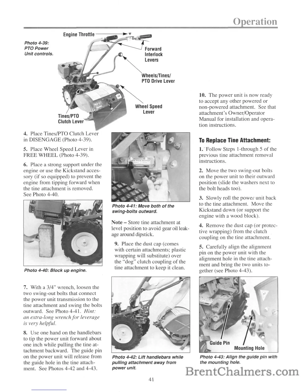
Photo
4-39:
PTOPower
Unit
controls.
Engine
Throttle
----=----..
6. Place a strong support under the
engine or use the Kickstand acces-
sory (if so equipped) to prevent the
engine from tipping forward when
the tine attachment
is
removed.
See Photo 4-40.
4. Place Tines/PTO Clutch Lever
in DISENGAGE (Photo 4-39).
5. Place Wheel Speed Lever in
FREE WHEEL (Photo 4-39).
7. With a 3/4" wrench, loosen the
two swing-out bolts that connect
the power unit transmission to the
tine attachment and swing the bolts
outward. See Photo 4-41. Hint:
an extra-long wrench
for
leverage
is very helpful.
8.
Use one hand on the handlebars
to
tip the power unit forward about
one inch while pulling the tine at-
tachment backward. The guide pin
on the power unit will release from
the guide hole
in
the tine attach-
ment. See Photos 4-42 and 4-43.
Photo
4-42:
Lift
handlebars while
pulling
attachment
away
from
power
unit.
Mounting
Hole
Photo
4-43:
Align
the
guide
pin
with
the
mounting
hole.
41



 To Next Page