Maintenance/Repairs
TIGHTEN
BOLTS
AND
NUTS
WARNING
To
help
avoid
personal
injury,
stop
the
engine,
remove
the
electric
start
key,
disconnect
the
spark
plug
wire
and
move
the
wire
away
from
the
spark
plug,
and
let
the
engine
muf-
fler
cool
before
inspecting
or
servicing
the
tiller
or
engine.
Check for loose
or
missing
hardware every ten (10) operating
hours. Failure to tighten or replace
fasteners can cause poor perfor-
mance, equipment damage or oil
leakage. See your Parts Catalog
for complete fastener descriptions.
Most hardware on your tiller is
visible. Pay particular attention to
hardware shown in Photos 5-1, 5-2,
5-3, and Figure 5-3A.
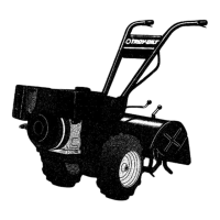
1. Check the transmission pulley
mounting bolt (Photo 5-1).
If
the
washer behind the bolt head
is
loose, the bolt needs tightening.
To
do this, first insert a punch or
thick screwdriver into the hole
next to the bolt and wedge the tool
against the side
of
the motor mount
casting. This "freezes" the pulley
while you tighten the bolt.
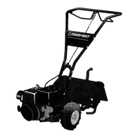
2. Check
jam
nut on left side
of
neutral plunger assembly (photo 5-
2).
If
loose, immobilize bolt head
with one wrench and use another
wrench to tighten the nut.
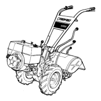
3. Check the three rear bearing
cap screws under the depth regula-
tor mounting bracket ("A", Photo
5-3).
If
any is loose, it can cause
an oil leak or drive shaft end play.
4. Check the five bolts securing
the tiller housing cover
to
the left
side
of
the transmission ("B"
in
Photo 5-3). Gear oil can leak from
a loose housing cover.
To
reach
the bolts, remove the left side tine
holder. See "Bolo Tine
Maintenance"
in
this Section for
tine holder removal directions.
5. Check both swing-bolts
("C",
Photo 5-3) that connect the power
unit transmission
to
the tine attach-
ment. Both bolts should be
checked every 2-1/2 hours
of
oper-
ation.
If
loose, wear can occur on
the locating pin on the power unit,
and cause enlargement
of
the locat-
ing hole in the tine attachment.
Using a torque wrench, tighten
these bolts to 70-to-80 ft.-Ibs.
6. Check the locknut that fastens
the shifting linkage to the eccentric
shifting lever ("D", Photo 5-3). Do
not tighten the locknut against the
eccentric lever. It should be very
close to, but not touching the lever.
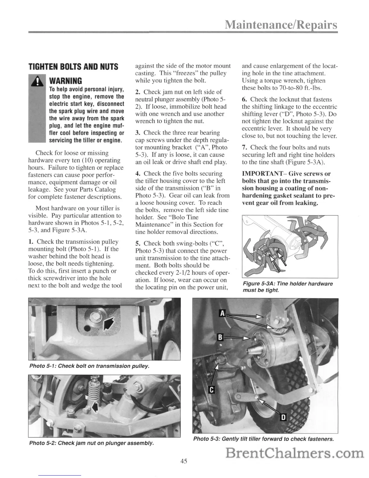
7. Check the four bolts and nuts
securing left and right tine holders
to the tine shaft (Figure 5-3A).
IMPORTANT-
Give screws
or
bolts
that
go into the transmis-
sion housing a coating
of
oon-
hardening
gasket sealant to pre-
vent
gear
oil from leaking.
Figure 5-3A: Tine
holder
hardware
must
be
tight.
Photo
5-1:
Check
bolt
on
transmission
pulley.
Photo
5-2:
Check
jam
nut
on
plunger
assembly.
45
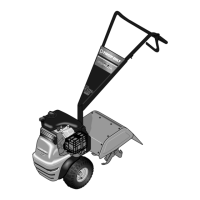
Photo
5-3:
Gently
tilt
tiller
forward
to
check
fasteners.