compound bonded to the disc rim.
Since this is a wearing part, it
should be inspected after every 30
operating hours.
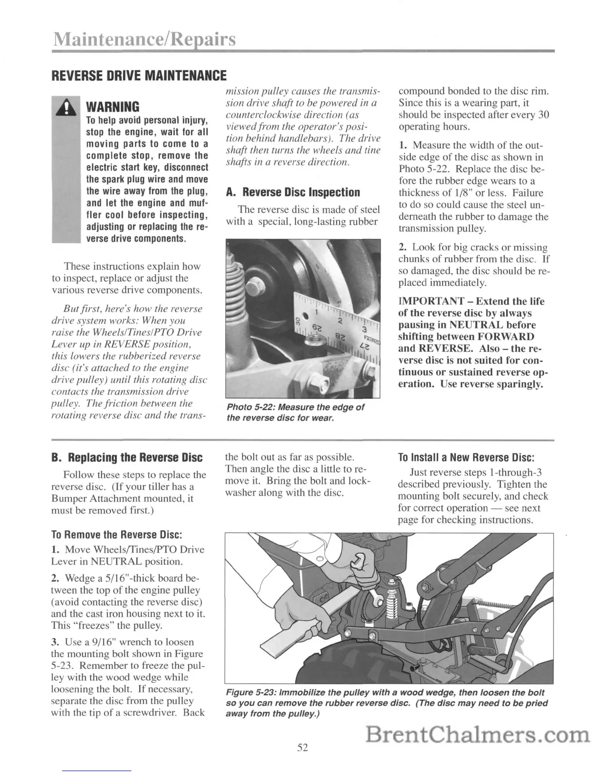
1. Measure the width
of
the out-
side edge
of
the disc as shown in
Photo 5-22. Replace the disc be-
fore the rubber edge wears to a
thickness
of
1/8" or less. Failure
to do so could cause the steel un-
derneath the rubber to damage the
transmission pulley.
2. Look for big cracks or missing
chunks
of
rubber from the disc.
If
so damaged, the disc should be re-
placed immediately.
IMPORTANT - Extend the life
of
the reverse disc by always
pausing in NEUTRAL before
shifting between FORWARD
and
REVERSE. Also - the re-
verse disc
is
not suited for con-
tinuous
or
sustained reverse op-
eration. Use reverse sparingly.
A.
Reverse
Disc
Inspection
The reverse disc is made
of
steel
with a special, long-lasting rubber
Photo 5-22: Measure the edge
of
the reverse
disc
for
wear.
WARNING
To
help
avoid
personal
injury,
stop
the
engine,
wait
for
all
moving parts
to
come
to
a
complete stop,
remove
the
electric
start
key,
disconnect
the
spark
plug
wire
and
move
the
wire
away
from
the
plug,
and
let
the
engine
and
muf-
fler
cool
before inspecting,
adjusting
or
replacing
the
re-
verse
drive
components.
REVERSE
DRIVE
MAINTENANCE
mission pulley causes the transmis-
sion drive
shaft to be powered in a
counterclockwise direction (as
viewedfrom the operator's posi-
tion behind handlebars). The drive
shaft then turns the wheels and tine
shafts in a reverse direction.
These instructions explain how
to inspect, replace or adjust the
various reverse drive components.
Butfirst, here's how the reverse
drive system works: When you
raise the Wheels/Tines/PTO Drive
Lever up
in
REVERSE position,
this lowers the rubberized reverse
disc (it's attached to the engine
drive pulley) until this rotating disc
contacts the transmission drive
pulley. The friction between the
rotating reverse disc and the trans-
B.
Replacing
the
Reverse
Disc
Follow these steps to replace the
reverse disc.
(If
your tiller has a
Bumper Attachment mounted, it
must be removed first.)
the bolt out as far
as
possible.
Then angle the disc a little
to
re-
move
it.
Bring the bolt and lock-
washer along with the disc.
To
Install a
New
Reverse
Disc:
Just reverse steps l-through-3
described previously. Tighten the
mounting bolt securely, and check
for correct operation - see next
page for checking instructions.
To
Remove
the
Reverse
Disc:
1. Move WheelsffineslPTO Drive
Lever
in
NEUTRAL position.
2. Wedge a 5/16"-thick board be-
tween the top
of
the engine pulley
(avoid contacting the reverse disc)
and the cast iron housing next to
it.
This "freezes" the pulley.
3. Use a 9/16" wrench to loosen
the mounting bolt shown in Figure
5-23. Remember to freeze the pul-
ley with the wood wedge while
loosening the bolt.
If
necessary,
separate the disc from the pulley
with the tip
of
a screwdriver. Back
Figure 5-23: Immobilize the
pulley
with a
wood
wedge, then
loosen
the
bolt
so
you
can remove the
rubber
reverse disc. (The
disc
may
need
to
be
pried
away
from the pulley.)
52


 To Next Page
 Loading...