EasyManua.ls Logo

Troy-Bilt 24A-204B063 - User Manual

Troy-Bilt 24A-204B063
24 pages
Print Icon
To Next Page IconTo Next Page
Loading...
Chipper Shredder
Vacuum
Model Number
204
OPERATOR’S MANUAL
IMPORTANT: READ SAFETY RULES AND INSTRUCTIONS CAREFULLY
TROY-BILT LLC P.O. BOX 361131 CLEVELAND, OHIO 44136-0019
Warning: This unit is equipped with an internal combustion engine and should not be used on or near any unimproved forest-
covered, brush-covered or grass-covered land unless the engine’s exhaust system is equipped with a spark arrester meeting
applicable local or state laws (if any). If a spark arrester is used, it should be maintained in effective working order by the operator.
In the State of California the above is required by law (Section 4442 of the California Public Resources Code). Other states may have
similar laws. Federal laws apply on federal lands. A spark arrester for the muffler is available through your nearest engine authorized
service dealer or contact the service department, P.O. Box 361131 Cleveland, Ohio 44136-0019.
PRINTED IN U.S.A.
FORM NO.
769-00170.fm
(4/02)
Question and Answer IconNeed help?

Do you have a question about the Troy-Bilt 24A-204B063 and is the answer not in the manual?

Overview

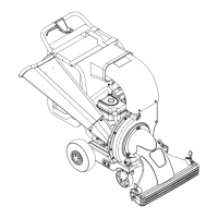
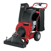
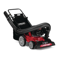
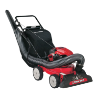
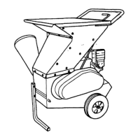
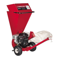
This document is the Operator's Manual for a Troy-Bilt Chipper Shredder Vacuum, Model Number 204. It provides essential information for assembly, operation, and maintenance of the unit.

Function Description

The Troy-Bilt Chipper Shredder Vacuum Model 204 is designed for yard waste management, specifically for shredding and chipping organic material. Its primary functions include:

  • Vacuuming: It can vacuum up yard waste such as leaves and pine needles through its nozzle for shredding.
  • Shredding: Material vacuumed through the nozzle or fed through the chipper chute is shredded by blades on the impeller assembly.
  • Chipping: The chipper chute allows for feeding twigs and small branches up to 3 inches in diameter into the impeller for chipping.
  • Collection: Shredded and chipped material is collected in an attached vacuum bag.

Important Technical Specifications

While specific engine details are referred to in a separate engine manual, the document highlights several key technical aspects and operational parameters:

  • Chipping Capacity: Capable of chipping branches up to 3 inches in diameter.
  • Tire Pressure (Pneumatic Tires Only): Maximum tire pressure is 30 psi. Equal tire pressure should be maintained at all times.
  • Impeller Assembly: Features rotating blades for shredding and chipping.
  • Spark Arrester: The internal combustion engine may require a spark arrester for use in certain areas (e.g., California, federal lands) to prevent fires on unimproved forest-covered, brush-covered, or grass-covered land. A spark arrester for the muffler is available through authorized service dealers.
  • Blade Torque: When reassembling chipper blades, hardware should be torqued to 250-300 in. lbs.
  • Impeller Assembly Bolt Torque: The hex bolt securing the impeller assembly to the crankshaft should be torqued to 550-700 in. lbs.

Usage Features

The chipper shredder vacuum incorporates several features to enhance usability and safety:

  • Nozzle: Designed for vacuuming yard waste like leaves and pine needles.
  • Nozzle Door Adjustment Levers: Located on each side of the nozzle door, these levers allow adjustment of the nozzle door for optimal ground clearance based on operating conditions.
  • Chipper Chute: A dedicated opening for feeding larger organic material for chipping.
  • Vacuum Bag: Collects processed material. It features a large zipper for easy emptying without removal from the unit. Straps secure the bag to the upper handle.
  • Drive Clutch Control: Located on the upper handle assembly, squeezing this control engages the rear wheels for self-propelled movement. Releasing it slows down or stops the wheel drive.
  • Caster Locks: Located on top of each front caster wheel, these locks allow positioning of the wheels (e.g., for straight-ahead operation or free swiveling).
  • Throttle Control Lever (Not Shown): Controls engine speed and stops the engine.
  • Starter Handle (Not Shown): Used to start the engine.
  • Safety Switch: A metal tab on the nozzle must depress this button for the engine to start, ensuring the nozzle is properly attached.
  • Portability: The unit can be pushed over yard waste using both hands on the upper handle.

Maintenance Features

The manual outlines a comprehensive maintenance schedule and procedures to ensure the longevity and performance of the unit:

  • Regular Inspections: Before starting, all bolts and screws should be checked for tightness. The machine should be visually inspected for damage at frequent intervals.
  • Safety Label Maintenance: Safety and instruction labels should be maintained or replaced as necessary.
  • Engine Maintenance: Refer to the separate engine manual for all engine-related issues, including oil level checks (before each use), air cleaner cleaning (every 25 hours or more frequently in dusty conditions), and spark plug cleaning and gap resetting (once a season).
  • Lubrication:
    • Rear wheels: Lubricate with light oil once a season.
    • Nozzle Door Adjustment Levers: Lubricate once a season with light oil.
    • Front Caster Wheels: Grease fittings are located on the swivel pins for easy lubrication.
  • Flail Screen Removal and Cleaning: If the discharge area becomes clogged, the flail screen can be removed by following specific instructions (removing screws, hex bolts, and lifting the screen from inside the housing) and cleaned by scraping or washing with water. Reassembly requires the curved side of the screen to face down.
  • Chipper Blade Sharpening or Replacement:
    • Requires disconnecting the spark plug wire, removing the flail screen, plastic belt cover, and access plate.
    • Blades can be removed using an allen wrench and a wrench.
    • When sharpening, the original angle of grind must be followed, and an equal amount of material removed from each blade.
    • Blades must be reassembled with the sharp edge facing upward.
  • Belt Removal and Replacement: This procedure is more complex, requiring an impeller removal tool (part number 753-0638) due to the engine's tapered crankshaft. It involves draining fuel and oil, removing the nozzle, vacuum bag, discharge chute, plastic belt cover, lower belt guard, safety switch, hex bolts securing the flail screen, outer housing, and the hex bolt securing the impeller assembly. The new belt is inserted around the transmission pulley, idler pulley, and impeller, ensuring it is routed inside all belt guards.
  • Storage: The unit should be cleaned thoroughly, wiped with an oiled rag to prevent rust, and stored in a clean, dry area. Engine storage instructions are detailed in the separate engine manual. It is crucial not to store the machine or fuel container indoors near open flames, sparks, or pilot lights.

Troy-Bilt 24A-204B063 Specifications

General IconGeneral
BrandTroy-Bilt
Model24A-204B063
CategoryChippers/Shredders
LanguageEnglish

Related product manuals