Maintenance
31
WHEEL DRIVE BELT
ADJUSTMENT
The wheel drive belt requires an
adjustment if loss of drive belt
tension (slippage) occurs. This is
most noticeable when more trac-
tion is required (such as going up
slopes).
To Test Wheel Traction
1. Park machine on a paved (con-
crete, etc.) surface with front edge
up against a sturdy wall, fence,
etc.
2. Put Gear Select Lever in No. 1
setting.
IMPORTANT: Do not park
against a painted or sided wall.
Testing the wheel drive system re-
quires machine to be forcibly
pushed against wall. Damage to
paint or siding could result.
3. With engine running, and ma-
chine placed firmly up against
wall, hold down Operator
Presence Control and fully engage
wheel drive by squeezing Wheel
Drive Control until it contacts
handlebar.
4. Wheels should slip on paved
surface. If they do not, an adjust-
ment is required.
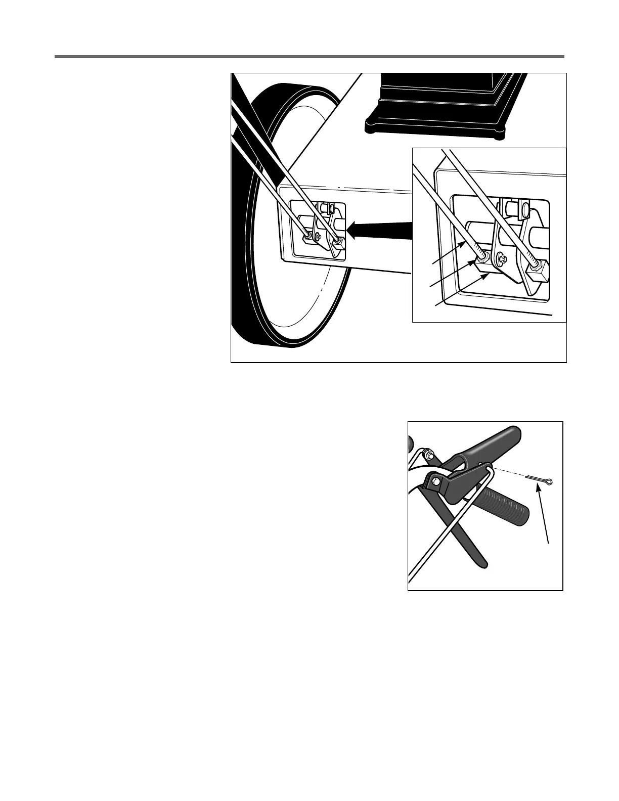
To Adjust Wheel Drive Belt
1. Stop engine, wait for all parts
to stop moving, and disconnect
spark plug wire.
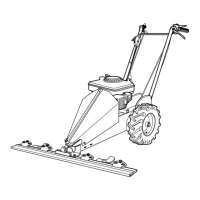
2. Remove cotter pin (A, Figure 5-
12A) from upper end of Wheel
Drive Control rod. Slide rod out of
lever assembly.
3. Loosen jam nut (D, Figure
5-12).
4. Thread rod (E, Figure 5-12) one
or two turns clockwise for more
tension or counterclockwise for
less tension.
5. Insert rod back into hole in
Wheel Drive Control lever and in-
stall cotter pin. Bend ends of cot-
ter pin to secure.
6. Retest belt traction. Repeat ad-
justment procedure, if necessary.
When adjustment is complete,
tighten jam nut (D) firmly against
block (B).
Figure 5-12: Wheel drive belt adjustment.
Figure 5-12A
E
D
B
A