Rg.
19
o
o
~.
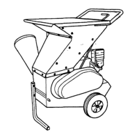
sure that the rubber band on the three bolts is not caught
between the bearing and the flangelle.
Fig.
21
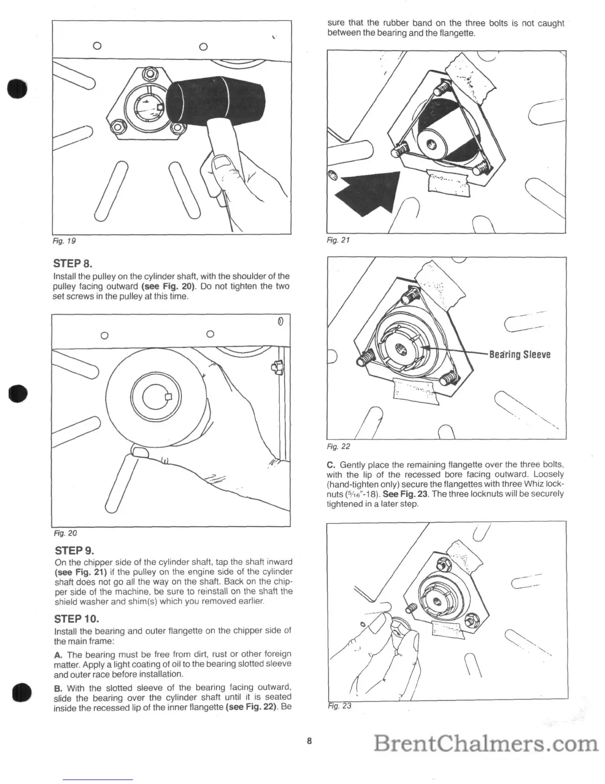
STEPS.
Install the pulley on the cylinder shaft, with the shoulder of the
pulley facing outward (see Fig. 20).
Do
not tighten the two
set screws
in
the pulley at this time.
c-·
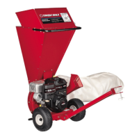
Bearing
Sleeve
Fig. 22
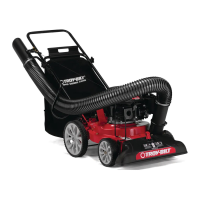
C.
Gently place the remaining f1angelle over the three bolts,
with the lip of the recessed bore facing outward. Loosely
(hand-tighten only) secure the f1angettes with three Whiz lock-
nuts
(5116"-18).
See Fig.
23.
The three locknuts will be securely
tightened
in
a later step,
o
o
Fig. 20
STEP 9.
On
the chipper side of the cylinder shaft, tap the shaft inward
(see Fig. 21)
if
the pulley on the engine side of the cylinder
shaft does not go all the way on the shaft. Back
on
the chip-
per side of the machine, be sure to reinstall on the shaft the
shield washer and shim(s) which you removed earlier.
STEP 10.
Install the bearing and outer f1angette on the chipper side of
the main frame:
A. The bearing must be free from dirt, rust or other foreign
matter. Apply a light coating of oil to the bearing slotted sleeve
and outer race before installation.
B. With the slotted sleeve of the bearing facing outward,
slide the bearing over the cylinder shaft until it
is
seated
inside the recessed lip of the inner flangette (see Fig. 22). Be
C-
'-"-
-'
8