D.
Cut and remove the rubber band, along with the strips of
tape
on
the edges of the inner flangette. Do not be concerned
if you cannot
remove all of the rubber band or tape.
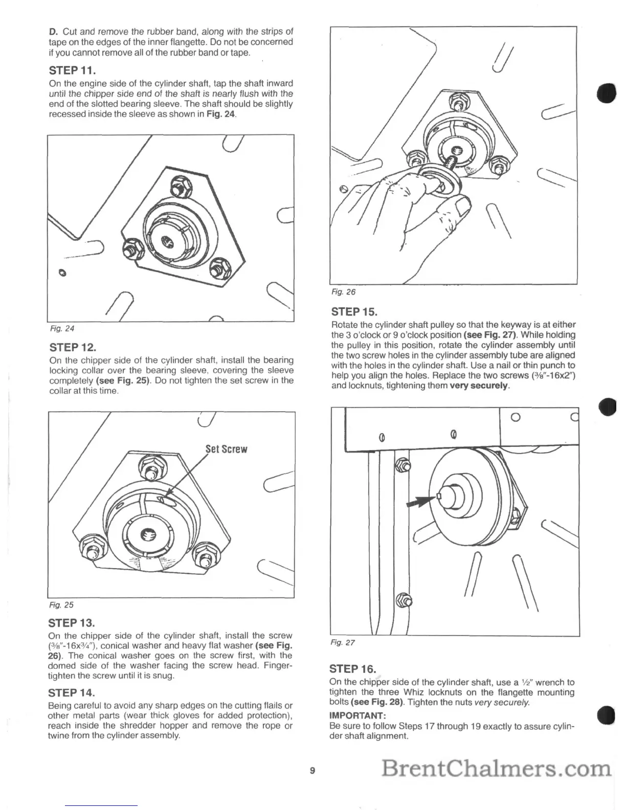
STEP 11.
On the engine side of the cylinder shaft, tap the shaft inward
until the chipper side end of the shaft is nearly flush with the
end of the slotted bearing sleeve. The shaft should be slightly
recessed inside the sleeve as shown
in
Fig. 24.
STEP 12.
On the chipper side of the cylinder shaft, install the bearing
locking collar
over the bearing sleeve, covering the sleeve
completely
(see
Fig. 25).
Do
not tighten the set screw
in
the
collar at this time.
Fig.
25
STEP 13.
On the chipper side of the cylinder shaft, install the screw
(3Je"-16x3f4"),
conical washer and heavy flat washer
(see
Fig.
26). The conical washer goes
on
the screw first, with the
domed side of the washer facing the screw head. Finger-
tighten the screw until it
is
snug.
STEP 14.
Being careful to avoid any sharp edges on the cutting flails or
other metal parts (wear thick gloves for added protection),
reach inside the shredder hopper and
remove the rope or
twine from the cylinder assembly.
9
!J
Fig.
26
STEP 15.
Rotate the cylinder shaft pulley so that the keyway is at either
the
3 o'clock or 9 o'clock position (see Fig. 27). While holding
the pulley
in
this position, rotate the cylinder assembly until
the two screw holes
in
the cylinder assembly tube are aligned
with the holes
in
the cylinder shaft. Use a nail or thin punch to
help you align the holes. Replace the two screws
(3Je"-16x2")
and locknuts, tightening them
very
securely.
o
Fig.
27
STEP 16.
On the chipper side of the cylinder shaft, use a
112"
wrench to
tighten the three Whiz locknuts
on
the f1angette mounting
bolts (see
Fig. 28). Tighten the nuts very securely.
IMPORTANT:
Be
sure to follow Steps 17 through 19 exactly to assure cylin-
der shaft alignment.
 Loading...